


36167-1-0316
Page 32
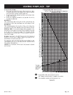
Determine Minimum Vent Height Above the Roof.
Locate and mark the center point of the vent pipe using a nail on
the underside of the roof. Drive the nail through the center point.
mark the outline of the roof hole around this center point.
NOTICE
: Size of the roof hole dimensions depend on the pitch of
the roof. There must be a 1 inch clearance (25 mm) to the vertical
pipe sections. This clearance is to all combustible material.
Cover the opening of the vent pipe and cut and frame the roof
hole. Use framing lumber the same size as the roof rafters and
install the frame securely. Flashing anchored to frame must
withstand high winds. The storm collar is placed over this joint to
make a water-tight seal. Non-hardening sealant should be used
to completely seal this flashing installation.
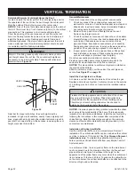
WARNINg
major U.S. building codes specify minimum chimney and/or
vent height above the roof top. These minimum heights are
necessary in the interest of safety. These specifications are
summarized in
figure 55.
VENT CAP
GAS VENT
24”
24”
MORE
THAN
10 FEET
figure 55
Note that for steep roof pitches, the vent height must be
increased. In high wind conditions, nearby trees, adjoining roof
lines, steep pitched roofs, and other similar factors can result in
poor draft, or down-drafting. In these cases, increasing the vent
height may solve this problem.
general Maintenance
Conduct an inspection of the venting system semi-annually.
1. Check any areas of the venting system exposed to the
elements for corrosion. Corrosion will appear as rust spots or
streaks and, in extreme cases, holes .Immediately Replace
any components that show signs of corrosion.
2. Remove the cap and shine a flashlight down the vent.
Remove any foreign material.
3. Check for evidence of excessive condensate, such as water
droplets forming in the inner liner and subsequently dripping
out at joints. Condensate can cause corrosion of caps,
pipe and fittings. excessive condensate may be caused by
having excessive lateral runs, too many elbows and exterior
portions of the system being exposed to cold weather.
4. Inspect joints to verify that no pipe sections or fittings have
been disturbed or loosened. Check mechanical supports,
such as wall straps or plumbers’ tape for rigidity.
Do not recess venting terminations in a wall or siding.
Provide a removable panel or other inspection means in the
enclosure for visual inspection of the flue connection.
NOTICE
: This also pertains to vertical vent systems installed on
the outside of the building.
Slide the vertical vent cap over the ends of the vent pipe and
secure.
See figure 57 on page 33.
Install the vent System in a Chase
A chase is a vertical box-like structure built to enclose the gas
fireplace and/or its vent system. Vertical vent runs on the outside
of a building may be, but are not required to be installed inside a
chase.
CAUTION
Treatment of firestop spacers and construction of the chase
may vary with the type of building. These instructions are
not substitutes for the requirements of local building codes.
Therefore, your local building codes must be checked to
determine the requirements for these steps.
NOTICE
:
It is always good building practice to insulate the chase
as you would the outside walls of the home. This is especially
important for cold climate installations. Install the vent system by
following the instructions in this manual after completion of the
chase framing. Build the chase large enough so the minimum
clearance of combustible materials (including insulation) to the
vent system are maintained.
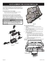
Installation of Vertical Inlet Baffle
Use the vertical inlet baffle only in a completely vertical vent
installation. The vertical inlet baffle can be used when the vertical
vent rise is between 10 feet and 40 feet.
for Simpson Duravent
installations only
: To maintain the yellow flame in the main
burner, purchase Vertical Inlet baffle from your empire Comfort
Systems dealer.
In a vertical vent rise, the rear (yellow) flame on the main burner
can be reduced due to the drawing action from the flue exhaust
pipe and the air inlet pipe. A decrease in the height or the
appearance of the yellow flame may occur when the vertical vent
rise is between 10 feet and 40 feet. To enhance the yellow flame
on the main burner, the vertical inlet baffle can be attached to the
direct vent high wind vertical cap.
vERTICAL TERMINATION
Содержание DVCD32FP3-2
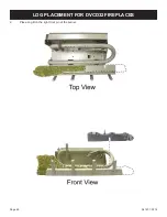
Страница 41: ...36167 1 0316 Page 41 1 Place Log A on the left front pin of the burner LOG PLACEMENT for DVCD32 fireplaces ...
Страница 42: ...36167 1 0316 Page 42 2 Place Log B on the right front pin of the burner LOG PLACEMENT for DVCD32 fireplaces ...
Страница 44: ...36167 1 0316 Page 44 4 Place Log D onto the rear log support LOG PLACEMENT for DVCD32 fireplaces ...
Страница 48: ...36167 1 0316 Page 48 Log placement is complete LOG PLACEMENT for DVCD32 fireplaces ...
Страница 51: ...36167 1 0316 Page 51 1 Place Log A on the left front pin of the burner LOG PLACEMENT For DVCD36 fireplaces ...
Страница 52: ...36167 1 0316 Page 52 2 Place Log B on the right front pin of the burner LOG PLACEMENT For DVCD36 fireplaces ...
Страница 54: ...36167 1 0316 Page 54 4 Place Log D onto the rear log support LOG PLACEMENT For DVCD36 fireplaces ...
Страница 57: ...36167 1 0316 Page 57 Log placement is complete LOG PLACEMENT For DVCD36 fireplaces ...
Страница 60: ...36167 1 0316 Page 60 1 Place Log A on the left front pin of the burner LOG PLACEMENT for DVCD42 fireplaces ...
Страница 61: ...36167 1 0316 Page 61 2 Place Log B on the right front pin of the burner LOG PLACEMENT for DVCD42 fireplaces ...
Страница 62: ...36167 1 0316 Page 62 3 Place Log D onto the rear log support LOG PLACEMENT for DVCD42 fireplaces ...
Страница 67: ...36167 1 0316 Page 67 Log placement is complete LOG PLACEMENT for DVCD42 fireplaces ...


