


36167-1-0316
Page 16
INSTALLATION
Install the Canopy
1. Retrieve canopy from the opening above the glass door.
2. Place the canopy above the firebox as shown in
figure 21.
NOTICE
: Fireplace heat shield will rest on top of the combustion
chamber inside of the open area between the top flue and
canopy.
3. Secure the canopy with two #8-18 x 1/2 inch pan head
screws provided in the hardware pack.
See figure 21.
HEAT SHIELD
CANOPY
figure 21
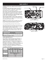
NOTICE
: maintain one inch of clearance to combustibles around
vertical vent pipe.
See figure 22.
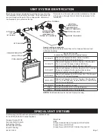
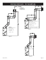
For horizontal vent systems,
maintain a minimum 1-inch clearance from the bottom and sides
of the vent to combustibles and a 3-
inch clearance above the
vent pipe
above the vent pipe to combustibles.
See figures 23
and 24.
Cold Climate Installation Recommendation
: Insulate the outer
walls to conform with applicable insulation codes if installing this
fireplace against a non-insulated exterior wall.
figure 22
vENT pIpE CLEARANCE
finishing
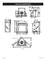
figure 7 on page 10
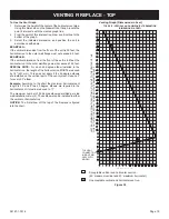
shows the minimum vertical and
corresponding maximum horizontal dimensions of mantels or
other combustible projections above the top front edge of the
fireplace.
only non-combustible materials may be used to cover the black
fireplace face.
WARNINg
Never obstruct or modify face of the fireplace. Improper
installation may cause a hazardous situation.
CAUTION
A 300°F minimum sealant material must be used if the joints
between the finished wall and the fireplace surround (top and
sides) are sealed. These joints are not required to be sealed.
only non-combustible material (use if needed), can be applied
to the fireplace surround. Consequences: Failure to use the
300°F minimum adhesive may allow the finishing material to
fall.
NOTICE
: For finishing to top of fireplace, refer to Figure 5, page
10.
6-5/8” Diameter
intake vent
4” Diameter flue
Combustibles NOT
allowed in shaded
area
Top of Vent
3” (76 mm)
1” (25 mm)
1”
(25 mm)
figure 23 - hard pipe vent Clearance
Содержание DVCD32FP3-2
Страница 41: ...36167 1 0316 Page 41 1 Place Log A on the left front pin of the burner LOG PLACEMENT for DVCD32 fireplaces ...
Страница 42: ...36167 1 0316 Page 42 2 Place Log B on the right front pin of the burner LOG PLACEMENT for DVCD32 fireplaces ...
Страница 44: ...36167 1 0316 Page 44 4 Place Log D onto the rear log support LOG PLACEMENT for DVCD32 fireplaces ...
Страница 48: ...36167 1 0316 Page 48 Log placement is complete LOG PLACEMENT for DVCD32 fireplaces ...
Страница 51: ...36167 1 0316 Page 51 1 Place Log A on the left front pin of the burner LOG PLACEMENT For DVCD36 fireplaces ...
Страница 52: ...36167 1 0316 Page 52 2 Place Log B on the right front pin of the burner LOG PLACEMENT For DVCD36 fireplaces ...
Страница 54: ...36167 1 0316 Page 54 4 Place Log D onto the rear log support LOG PLACEMENT For DVCD36 fireplaces ...
Страница 57: ...36167 1 0316 Page 57 Log placement is complete LOG PLACEMENT For DVCD36 fireplaces ...
Страница 60: ...36167 1 0316 Page 60 1 Place Log A on the left front pin of the burner LOG PLACEMENT for DVCD42 fireplaces ...
Страница 61: ...36167 1 0316 Page 61 2 Place Log B on the right front pin of the burner LOG PLACEMENT for DVCD42 fireplaces ...
Страница 62: ...36167 1 0316 Page 62 3 Place Log D onto the rear log support LOG PLACEMENT for DVCD42 fireplaces ...
Страница 67: ...36167 1 0316 Page 67 Log placement is complete LOG PLACEMENT for DVCD42 fireplaces ...


