


Menu 2
Parameter
structure
Keypad and
display
Parameter
x.00
Parameter
description format
Advanced parameter
descriptions
Macros
Serial comms
protocol
Electronic
nameplate
Performance
RFC mode
46
Unidrive SP Advanced User Guide
www.controltechniques.com Issue Number: 10
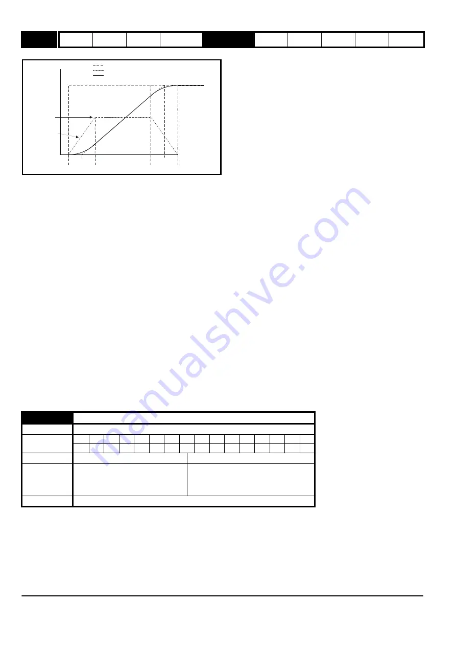
The time taken in seconds for the ramp output to change by frequency (
Δ
f*) or speed (
Δ
w*) is given below. Two cases are given because the total
ramp time must be calculated with a different equation depending on whether the acceleration is able to reach the selected ramp rate (A) or not. If the
required change is small the selected ramp rate is not reached and the ramp does not include the central linear ramp region. If the required change is
larger the ramp does include the central linear region as shown in the diagram above.
Frequency (Open-loop mode)
Δ
f*
linear
= 100 x J / A
2
where:
A is the selected ramp rate in s / 100Hz
J is parameter Pr
2.07
, the S ramp acceleration limit in s
2
/ 100Hz
If the required change is less than
Δ
f*
linear
then T
Ramp1
should be used, but if the speed change is greater or equal to
Δ
f*
linear
T
Ramp2
should be used.
T
Ramp1
= 2
√
(
Δ
f* x J / 100)
T
Ramp2
= (
Δ
f* x A / 100) + (J / A)
Speed (Closed-loop vector and servo)
Δ
w*
linear
= 1000 x J / A
2
where:
A is the selected ramp rate in s / 1000rpm
J is Pr
2.07
, the S ramp acceleration limit in s
2
/ 1000rpm
If the required change is less than
Δ
w*
linear
then T
Ramp1
should be used, but if the speed change is greater or equal to
Δ
w*
linear
T
Ramp1
should be
used.
T
Ramp1
= 2
√
(
Δ
w* x J / 1000)
T
Ramp2
= (
Δ
w* x A / 1000) + (J / A)
The default values for the ramp rate and S ramp acceleration limit have been chosen such that for the default maximum speed, the curved parts of the
S ramp are 25% of the original ramp if S ramp is enabled. Therefore the ramp time is increased by a factor of 1.5.
This voltage is used as the control level for standard ramp mode. If this parameter is set too low the machine will coast to rest, and if it is set too high
and no braking resistor is used the drive may give an OU trip. The minimum level should be greater than the voltage produced on the DC bus by the
highest supply voltage. Normally the DC bus voltage will be approximately the rms supply line voltage x
√
2.
2.08
Standard ramp voltage
Drive modes
Open-loop, Closed-loop vector, Servo
Coding
Bit
SP
FI
DE Txt VM DP ND RA NC NV
PT
US RW BU PS
1
1
1
1
1
Range
Open-loop, Closed-loop vector, Servo
0 to DC_VOLTAGE_SET_MAX V
Default
Open-loop, Closed-loop vector, Servo
200V rating drive: 375
400V rating drive: EUR: 750 / USA: 775
575V rating drive: 895
690V rating drive: 1,075
Update rate
Background read
t
Acceleration
Actual Speed
Programmed
ramp rate
T
T
T/2
T/2
T/2
T/2
S ramp
acceleration
ramp
Demanded Speed
Содержание unidrive sp
Страница 419: ......
Страница 420: ...0471 0002 10 ...


