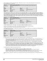

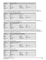
Value
Text
Description
0
Ur.S
Stator resistance and voltage offset measured at each start
1
Ur
No measurements
2
FD
Fixed boost mode.
3
Ur.Auto
Stator resistance and voltage offset measured at first drive
enable
4
Ur.I
Stator resistance and voltage offset measured at each power-up
5
SrE
Square law characteristic
6
Fd.tap
Fixed boost with zero slip at zero reference
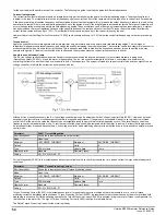
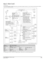
The
Open-loop Voltage Mode
(05.014) defines the voltage output mode, as given below. It should be noted that the maximum output voltage of the drive is
limited to a level just below
D.c. Link Voltage
(05.005) / √2. Therefore, if the drive is being supplied via its own rectifier input stage the output voltage is limited
to a level just below that of the supply voltage. If the drive is operating in voltage mode the output voltage is limited to
Motor Rated Voltage
(05.009) or the
maximum possible output voltage whichever is the lowest (also refer to
Over Modulation Enable
(05.020)).
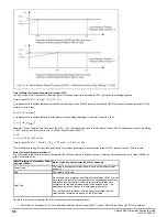
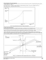
0: Ur S (Resistance compensation, stator resistance measured at each start)
Resistance compensation is a form of stator flux oriented sensorless motor control. A linear frequency to voltage characteristic is used where the drive output
voltage is increased from 0V to
Motor Rated Voltage
(05.009). as the |
Output Frequency
(05.001)| increases from 0Hz to
Motor Rated Frequency
(05.006).
When the |
Output Frequency
(05.001)| is above
Motor Rated Frequency
(05.006) the output voltage is limited to
Motor Rated Voltage
(05.009). Vector based
stator resistance compensation is applied below
Motor Rated Frequency
(05.006) / 4 and then this is tapered off from
Motor Rated Frequency
(05.006) / 4 to
Motor Rated Frequency
(05.006) / 2. This method controls the flux level correctly in the motor in the steady state provided the correct value of
Stator Resistance
(05.017) is used.
If slip compensation is not being used (see
Motor Rated Frequency
(05.006) ) then additional voltage compensation can be applied below
Motor Rated Frequency
(05.006) / 10 to have an additional torque boost at very low frequencies, see
Low Frequency Estimator Threshold,
Low Frequency Torque adjustment
(05.084).
The
Stator Resistance
(05.017) is measured each time the drive is started. This test can only be done with a stationary motor where the flux has decayed to
zero. Therefore this mode should only be used if the motor is guaranteed to be stationary each time the drive is enabled. To ensure that the measurement is
not carried out before the flux has decayed, there is a period of one second after the inverter has been disabled during which the test is not carried out if the
drive is re-started. The
Stator Resistance
(05.017) is not automatically saved in non-volatile memory after each test.
1: Ur (Resistance compensation with no stator resistance measurement)
Resistance compensation is used as in Ur S mode, but the
Stator Resistance
(05.017) is not measured.
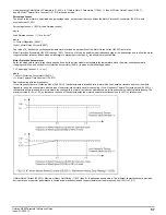
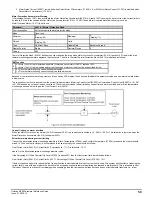
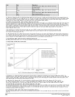
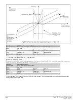
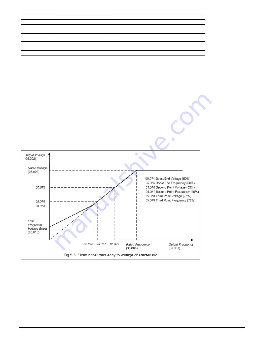
2: Fixed (Fixed boost with linear characteristic)
A fixed frequency to voltage characteristic is used as shown above where the voltage at 0Hz is defined by
Low Frequency Voltage Boost
(05.015). The
voltage characteristic moves linearly with output frequency passing through four points determined by [
Boost End Voltage
(05.074) and
Boost End Frequency
(05.075)], [
Second Point Voltage
(05.076) and
Second Point Frequency
(05.077)],
Third point voltage
(05.078) and
Second Point Frequency
(05.077), and
[
Motor Rated Voltage
(05.009) and
Motor Rated Frequency
(05.006)].
By default
Boost End Frequency
(05.075) is set to half the
Motor Rated Frequency
(05.006),
Second Point Frequency
(05.077) is set 55%
and
Third point frequency
(05.079) is set to 75%. Similarly by default
Boost End Voltage
(05.074) is set at half the
Motor Rated Voltage
(05.009),
Second Point Voltage
(05.076) 55% and
Third point voltage
(05.078) is set to 75%. This is to produce the same characteristic as SK by default.
3: Ur Auto (Resistance compensation, stator resistance measured on first start)
Resistance compensation is used as in Ur S mode, but the
Stator Resistance
(05.017) is only measured once when the drive is first enabled. After the test has
been completed successfully the mode is changed to Ur mode and
Stator Resistance
(05.017) is saved to non-volatile memory. If
Parameter Cloning
(11.042)
is set to 3 or 4 the
Stator Resistance
(05.017) is also written to a non-volatile media card fitted in the drive. If the test fails the mode is changed to Ur mode,
but
Stator Resistance
(05.017) is not updated.
4: Ur I (Resistance compensation, stator resistance measured at power-up)
Resistance compensation is used as in Ur S mode, but the
Stator Resistance
(05.017) is only measured when the drive is enabled for the first time after each
power-up.
68
Unidrive M200 Parameter Reference Guide
Issue: 01.05.00.10
Содержание unidrive m200
Страница 1: ...Parameter Reference Guide Unidrive M200 Open loop Mode Issue 01 05 00 10 ...
Страница 29: ...Menu 2 Frequency Ramps Mode Open loop Unidrive M200 Parameter Reference Guide Issue 01 05 00 10 29 ...
Страница 30: ...30 Unidrive M200 Parameter Reference Guide Issue 01 05 00 10 ...
Страница 83: ...Enable logic Unidrive M200 Parameter Reference Guide Issue 01 05 00 10 83 ...
Страница 100: ...Menu 7 Analog I O Mode Open loop 100 Unidrive M200 Parameter Reference Guide Issue 01 05 00 10 ...
Страница 113: ...Menu 8 Digital I O Mode Open loop Unidrive M200 Parameter Reference Guide Issue 01 05 00 10 113 ...
Страница 125: ...Unidrive M200 Parameter Reference Guide Issue 01 05 00 10 125 ...
Страница 144: ...Menu 10 Status and Trips Mode Open loop 144 Unidrive M200 Parameter Reference Guide Issue 01 05 00 10 ...
Страница 145: ...Unidrive M200 Parameter Reference Guide Issue 01 05 00 10 145 ...
Страница 204: ...204 Unidrive M200 Parameter Reference Guide Issue 01 05 00 10 ...


