


The use of pliers is recommended for the beading process.
When threading the glazing beading along the bars, there is a tendency for it to stretch and later
contract. It is therefore advisable to have the beading protruding approx. 25mm at each end of each
bar which can then be pushed back at either end if necessary. Before assembly, you must ensure
that the beading is flush with the ends of the bar. It may be necessary to trim the beading to size.
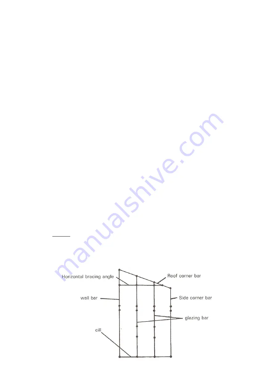
2.
The longer of the other bars is the wall bar and has only one groove for glazing bead,
while the glazing bar has two grooves for glazing bead. Slide glazing bead in to these
channels in the same way as for the corner bars.
3.
The corner bars now need to be distinguished between a roof corner bar and a side corner
bar.
*
The roof corner bar is 1944mm long and has 4 holes in the flange, and is mitred at
both ends.
*
The side corner bar is 1795mm long and has 1 hole in the flange, and is mitred at
one end only.
Having determined which corner bar is the roof and side, you must now establish which way round
they go for assembly purposes.
* Side corner bar
The end that is mitred and with only one hole in the flange near to the mitre is the
top of the bar. The bolt slots are to be on the inside for assembly purposes.
* Roof corner bar
There is a mitre at both ends and 4 holes in the flange. The smallest of the two
mitres is to be the top of the bar i.e. it is to be placed nearest to the ridge. The
other end with the most severe mitre will go to the eave to marry up with the side
corner bar.
4.
Lay out the component parts on the ground with the bolt slots uppermost in the positions
shown below. Ensure that the wall bar is laid on the ground in a way so that the beaded
section of the bar is on the inside for glazing purposes.
Now you must add the nuts and bolts to the bars. The diagram below illustrates the bolt configura-
tion for the rear end gable. Where a Dot appears below, a bolt with a finger tip tightened nut should
be slid along the bolt slot of the bar. In the case of the corner bars, the bolt should be slid along the
lower bolt slot which faces up, and not the bolt slot facing sideways. In to the bolt slot facing side-
ways on each corner bar, slide 2 bolts – 1 top and 1 bottom, put a nut on and finger tip tighten, these
will be used later in the general assembly.
Содержание KENSINGTON 10 x 6
Страница 1: ......
Страница 2: ......
Страница 3: ......
Страница 17: ...DOOR FRAME...
Страница 36: ...6 WIDE LT TOUGHENED GLASS PLAN Glass pane for standard door on gable end Louvre on rear end...
Страница 39: ...OPTIONAL EXTRAS RAIN WATER KIT FOR GUTTERING...
Страница 40: ...ELITE 1407...


