15 – Final Assembly
●
31
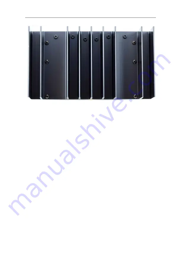
Figure 32. Rear view of the heatsink after 12 screws are tightened.
15 – Final Assembly
The finished protection PCB can now be placed on the six 30-mm
standoffs and fastened with six M3 nuts.
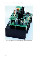
The following three images show the (almost) finished module. Only
the connection of the +40 V power supply between the two PCBs (K2
to K5) is missing. The photos show the construction of the first com-
pleted prototype for measurements conducted at Elektor Labs. At this
stage LED5 wasn’t fitted on the protection PCB.
Содержание Fortissimo-100
Страница 7: ...Elektor Fortissimo 100 Power Amplifier Kit 8 Figure 2 The resistors and small capacitors in the kit ...
Страница 10: ... 11 Figure 7 The mechanical parts in the kit Figure 8 The SK104 heatsinks in the kit 1 Kit Contents ...
Страница 31: ...Elektor Fortissimo 100 Power Amplifier Kit 32 Figure 33 Left side view of the Fortissimo 100 Power Amplifier ...
Страница 32: ...15 Final Assembly 33 Figure 34 Right side view of the Fortissimo 100 amplifier ...
Страница 48: ...23 Schematics and PCB Layouts 49 Figure 46 Bottom side copper layout for both PCBs 210364 1 v1 1 ...


