background image

Elektor Fortissimo-100 Power Amplifier Kit

 12

Figure 9. The SK53-100-SA heatsink in the kit. 

2 – Introduction

Notice: It is strongly advised to closely read the entire Construction 
Manual before starting the construction of the amplifier.

The design, especially the placement of the power transistors T17–T22 
and the PCB, is aimed at easy replication. The mechanical work need-
ed should be possible with simple tools and basic skills like drilling 12 
3-mm holes to mount the transistors and fasten the PCB in parallel 
with the back of the heatsink. The fin spacing of the selected heatsink 
(type SK53-100-SA from Fischer Elektronik) is sufficient for the heads 
of the black 3-mm screws while also allowing room for some error. 
The PCB is mounted onto the heatsink with six 10-mm long metal 
male-female standoffs with 3-mm thread. The 6 transistors of the out-
put stage are electrically insulated with ceramic (Al

2

O

3

) pads, marked 

by a lower thermal resistance than comparable types. During the final 
stage of construction, apply some thermal grease on the back of the 
transistors and on the sides of the pads placed against the heatsink. 
Only a very thin layer is required! Take precautions not to get the ther-
mal grease on your fingers as most types are toxic.

The DC protection and relay circuit are placed on a second, smaller 
PCB placed in parallel with the amplifier PCB. Six 30-mm long male-fe-
male metal standoffs ensure a solid construction. Standoffs K3 and K4 

Содержание Fortissimo-100

Страница 1: ...books Ton Giesberts Construction Manual Elektor Fortissimo 100 Power Amplifier Kit 4 6 p a g e s i n s t r u c t i o n s jump st rter from project to product ...

Страница 2: ... 3 Elektor Fortissimo 100 Power Amplifier Kit Designed by Ton Giesberts Elektor Labs Construction Manual V1 0 date September 8 2022 Elektor International Media b v ...

Страница 3: ...Elektor Fortissimo 100 Power Amplifier Kit 4 Notice This manual is only available as a downloadable PDF at www elektor com 20273 ...

Страница 4: ... Leads 16 6 Locating and Drilling Holes in the Heatsink for the Transistors 17 7 Small Resistors and Diodes 19 8 Axial Power Resistors and IC Socket 20 9 Small Capacitors and Input Terminal Pins 20 10 Finishing the Assembly of the Protection PCB 21 11 Small Transistors LEDs Radial Power Resistors and Large Capacitors 22 12 Placing the Loudspeaker Signal Through Contact Standoffs 23 13 Transistors ...

Страница 5: ...en consent from the Publisher Patent protection may exist in respect or circuits and devices described here The Publisher does not accept responsibility for failing to identify such patent s or other protection The Publisher also disclaims any responsibility for the safe and proper function of reader assembled projects based upon or from schematics or information published in or in relation with t...

Страница 6: ...is document Section 19 Construction Manual Downloadable PDF Figure 1 Contents of the Fortissimo 100 Power Amplifier kit as supplied by the Elektor Store Before embarking on the construction of the Kit be sure to inspect the contents using the Bill of Materials and the photos that follow Check that all parts are supplied and in usable condition ...

Страница 7: ...Elektor Fortissimo 100 Power Amplifier Kit 8 Figure 2 The resistors and small capacitors in the kit ...

Страница 8: ... 9 1 Kit Contents Figure 3 The electrolytic capacitors in the kit Figure 4 The small transistors diodes and other parts in the kit ...

Страница 9: ...Elektor Fortissimo 100 Power Amplifier Kit 10 Figure 5 The larger transistors Figure 6 The ceramic pads washers and the relay in the kit ...

Страница 10: ... 11 Figure 7 The mechanical parts in the kit Figure 8 The SK104 heatsinks in the kit 1 Kit Contents ...

Страница 11: ...s sufficient for the heads of the black 3 mm screws while also allowing room for some error The PCB is mounted onto the heatsink with six 10 mm long metal male female standoffs with 3 mm thread The 6 transistors of the out put stage are electrically insulated with ceramic Al2O3 pads marked by a lower thermal resistance than comparable types During the final stage of construction apply some thermal...

Страница 12: ...rent values or shapes in your kit This is because the amplifier shown was a first prototype for testing 3 Tools Needed Soldering equipment for through hole components Soldering iron rated at 100 watts minimum Also recommended is an ex tra long tip for soldering the transistors in the output stage Small pliers with flat jaws Pliers with special jaws for pressing a thermal relief bend in the leads o...

Страница 13: ... Amplifier Kit 14 4 Locating and Drilling Holes in the Heatsink for the PCB Standoffs Figure 10 The bare PC boards for the amplifier and protection circuitry as supplied in the kit Figure 11 Amplifier PCB used as drilling template ...

Страница 14: ...uts of the amplifier they must never be in electrical contact with the heatsink All six holes are located at ample distances from the heatsink fins to allow room for the screw heads including a small error margin Figure 12 Standoffs secured in place for the PCB to be mounted After the six 3 mm holes are drilled the six 10 mm standoffs are mounted on the heatsink and fastened with the black 12 mm M...

Страница 15: ...e transistors Figure 13 To avoid excessive force exerted from the leads to the package of the large power transistors use a 2 mm drill bit and a small vice Gently clamp the pins and the drill bit between the vice jaws Use a flat piece of material to bend all leads toward the front of the transistor Bending the leads of the smaller TO 220 packages can be done with flat jaw pliers Bend them at 1 mm ...

Страница 16: ... holes Also the ceramic insulation pads must be placed between the transistors and the heatsink since this can affect the exact position of the holes In this prototype the four holes for the power transistors are approximately 8 8 mm from the edge of the heatsink and the smaller transistors at 11 5 mm However this can vary and the exact location depends on the exact position of the bend in the tra...

Страница 17: ...drilled prototype Figure 16 Six 3 mm holes drilled for the transistors in the output stage After drilling the holes place the transistors in position with their screws It s not necessary to secure them with nuts Check if the PCB is a perfect fit with all leads and the six standoffs through their holes ...

Страница 18: ... Diodes 19 Now almost all parts can be fitted on the PCBs Start with the lowest components small resistors and diodes D1 D5 7 Small Resistors and Diodes Figure 17 The small resistors and diodes soldered onto the two boards ...

Страница 19: ...t 20 8 Axial Power Resistors and IC Socket Figure 18 Axial power resistors and 8 pin IC socket pos IC3 soldered onto the amp board 9 Small Capacitors and Input Terminal Pins Figure 19 The small capacitors also soldered onto the amplifier board ...

Страница 20: ...12 C2 C13 C14 C18 C19 C29 C17 C33 C28 Next the larger higher value capacitors C6 C7 C8 C9 C30 C31 C34 input terminal pins C1 10 Finishing the Assembly of the Protection PCB Figure 20 To finish the protection board solder the relay and the air cored inductor onto the board Figure 21 The completed protection board PCB 210364 1 v1 1 shown ...

Страница 21: ...bove R76 and check if the distance of the two ends corresponds with the footprint and are in line R76 suppresses possible ringing Use a hobby knife to scrape the enamel insulation off the inductor wire ends then pre tin them lightly LED5 is to be mounted on the front of the enclosure of the amplifier and is connected by thin stranded wire if so desired 11 Small Transistors LEDs Radial Power Resist...

Страница 22: ...e end of this document for details Section 17 Selecting BC546B BC556B for Differential Pairs When soldering the pairs make sure the flat sides remain in good contact since a maxi mum contact surface guarantees proper thermal coupling Next the radial power resistors R50 R51 R54 R55 capacitors C15 and C16 and capacitors C20 C27 can be fitted and soldered 12 Placing the Loudspeaker Signal Through Con...

Страница 23: ...screw The two metal standoffs that connect the amplifier output lines of the main PCB to the smaller PCB above it can now be fitted and secured with an 8 mm long M3 cheese head screw 13 Transistors T13 T16 and the Small Heatsinks Figure 25 Special pliers and an example of the thermal relief bend in the leads needed for T13 T16 ...

Страница 24: ...d by temperature changes It s best to make a small bend in the leads away from the heatsink Figure 25 shows the special pliers required to do this and a success fully shaped transistor Alternatively pliers with round jaws can be used for this job The bend must be close enough to the package per mitting the pins of the transistors to pass through the PCB Figure 26 Two transistors mounted at each si...

Страница 25: ...tic Place the head of the screw toward the input of the PCB but don t tighten the screw yet You can only use a screwdriver from this side to fasten the screw Place an M3 metal washer between the head of the screw and the transistor Figure 26 shows the transistors secured to the small heatsink Solder the pins of the two heatsinks to the PCB first and only then tighten the screws of the transistors ...

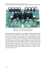
Страница 26: ...ix output stage transistors fastened temporarily with screws and nuts to enable them to be soldered Also the PCB is fixed onto the 10 mm long standoffs on the heatsink with 30 mm long standoffs or use nuts for now Also place the ceramic washers for the transistors and the insulating bushes for the TO 220 transistors since all of this can influence the exact location of each transistor ...

Страница 27: ... top When this is done remove the screws that hold the transistors first and then the standoffs that hold the PCB Carefully take the PCB off the heatsink and make sure not to bend the transistors Now the transistors are attached to the PCB at their final position Solder the rest of the leads from the bottom side 2 way screw terminal block K2 was not soldered yet to give better access to the leads ...

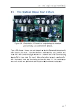
Страница 28: ...heatsink upright with the holes for the transistors at the top Insert the six black screws halfway through the heatsink The 16 mm black screws take T19 T22 and the 12 mm black screws take T17 and T18 Slide the ceramic washers with the greased side over the screws against the heatsink as shown in Figure 30 in the prototype 6 off black 16 mm screws were used ...

Страница 29: ...s through the transistor holes while the ceramic washers remain in position Place and tighten the four 30 mm stand offs and the two M3 nuts to fix the PCB securely to the heatsink Also use M3 washers to fix the four power transistors and don t forget the insulating bushes for T17 and T18 type IB 6 from Fischer Elektronik or similar Tighten the six screws Place IC3 in its socket Figure 31 shows the...

Страница 30: ...six 30 mm standoffs and fastened with six M3 nuts The following three images show the almost finished module Only the connection of the 40 V power supply between the two PCBs K2 to K5 is missing The photos show the construction of the first com pleted prototype for measurements conducted at Elektor Labs At this stage LED5 wasn t fitted on the protection PCB ...

Страница 31: ...Elektor Fortissimo 100 Power Amplifier Kit 32 Figure 33 Left side view of the Fortissimo 100 Power Amplifier ...

Страница 32: ...15 Final Assembly 33 Figure 34 Right side view of the Fortissimo 100 amplifier ...

Страница 33: ... Figure 35 Broadside view of the Fortissimo 100 s output stage Figures 33 34 and 35 show the assembly and initial wiring of the first prototype for measurements Figure 36 The finished Fortissimo 100 Audio Power Amplifier that was used for testing ...

Страница 34: ...e remainder of the enclosure s top and bottom sides should have plenty of ventilation holes considering that the power supply will get hot too To keep the length of the supply wires to an absolute minimum the output of the power supply should be positioned as close as possible to screw terminal block K1 on the amplifier PCB The type SMPS800RE switch mode power supply SMPS is recommended for use Ac...

Страница 35: ...erential input stages simple circuits can be built on a breadboard Use SIL or IC sockets to easily swap TUT s or use a solderless breadboard For lowest offset it s best to use two transistors placed or clamped against each other and then meas ure the potential difference between the 3 3 kΩ resistors as pictured in Figure 37 The base currents can be measured across the 10 kΩ resistors Preferably th...

Страница 36: ...f the power supply each time when removing or inserting an other transistor Measure and make a note of each offset per newly in serted transistor Wait for the offset to settle to a stable reading Place all available transistors in a piece of anti static foam and use pliers to swap them on the breadboard If not the body heat of your fingers will seriously affect the time it takes for the reading to...

Страница 37: ...hree wires from the power supply to the amplifier closely together This will minimize the risk of magnetic fields interfering with the amplifier Recommendation also clamp on a sufficiently large split ferrite core for EMI suppression making sure it fits around all three wires to enable it to function as a common mode filter At the mains side of the SMPS800RE a small screw terminal for a pow er swi...

Страница 38: ...max R19 R22 R48 R49 R52 R53 220 Ω 1 0 6 W R21 R24 33 Ω 1 0 6 W R25 R26 56 Ω 1 0 6 W R29 R30 R35 R36 27 Ω 1 0 6 W R31 R37 1 Ω 1 0 6W R32 R38 1 5 kΩ 5 1 W metal film or metal oxide body size 5 x 12 mm max In KIT MFP1 1K5 JI TT Electronics Welwyn small size 6 2 x 2 5 mm R39 R40 R41 R42 22 Ω 1 0 6 W R43 6 8 kΩ 5 1 W metal film or metal oxide body size 5 x 12 mm max R44 R47 680 Ω 5 3 W metal film or me...

Страница 39: ... µF 20 16 V D 6 3 mm preferably 105 C C10 C11 220 pF 5 100 VDC pitch 5 mm C0G NP0 body size 2 5 x 7 2 mm max C12 100 pF 5 100 V pitch 5 mm PP body size 4 5 x 7 2 mm max FKP2D001001D00JSSD Wima C13 C14 C18 C19 C29 100 nF 5 100 VDC pitch 5 mm PET body size 2 5 x 7 2 mm max C15 C16 680 µF 20 35 VDC D 12 5 mm pitch 5 mm 5000h 105 C 35ZL680MEFC12 5X20 Rubycon C17 100 nF 5 160 VDC pitch 5 mm PP body siz...

Страница 40: ... LED3 LED4 LED red 2 x 5 mm rectangular MCL453MD Multicomp Pro LED5 LED green 5 mm T 1 3 4 5 mm T1 T2 T6 T7 T9 T10 T23 T26 T27 BC546B TO 92 T3 T4 T5 T8 T11 T12 T24 BC556B TO 92 T13 T14 KSA1381 TO 126 T15 T16 KSC3503 TO 126 T17 MJE15032G TO 220 T18 MJE15033 G TO 220 T19 T20 NJL3281DG TO 264 5 LEAD T21 T22 NJL1302DG TO 264 5 LEAD T25 BS170 TO 92 IC1 IC2 LM334Z TO 92 IC3 OPA177FP DIP 8 Miscellaneous ...

Страница 41: ... steel 6 x metal standoff 10 mm M3 male female PCB to heatsink HS1 HS2 Heatsink 9 C W H 50 8 mm SK 104 50 8 ST Fischer Elektronik T17 T22 Heatsink 0 6 C W 100x180x48mm SK53 100 SA Fischer Elektronik T19 T20 T21 T22 Ceramic thermal pad 23 x 20 mm x 2 mm SL 012 AL20 Silfox T17 T18 Ceramic thermal pad 18 x 12 x 1 5 mm SL 019 AL15 Silfox T17 T18 Insulating bushing TO 220 IB 6 Fischer Elektronik IC3 DI...

Страница 42: ... 50 W 8 Ω Open loop bandwidth 20 kHz Open loop gain 140 000 8 Ω load Slew rate 45 V µs Rise time 1 5 µs Signal to noise ratio 103 dB B 22 Hz 22 kHz linear Referred to 1 W 8 Ω 106 dBA Harmonic distortion plus noise 0 0008 1 kHz 1 W 8 Ω B 22 kHz 0 0016 1 kHz 1 W 8 Ω B 80 kHz 0 0016 20 kHz 1 W 8 Ω B 80 kHz 0 0008 1 kHz 50 W 8 Ω B 22 kHz 0 0008 1 kHz 50 W 8 Ω B 80 kHz 0 002 20 kHz 50 W 8 Ω B 80 kHz 0 ...

Страница 43: ...8 K9 315 20 kHz 8 Ω Power supply detection 36 5 V Off Positive supply only slightly temperature dependent 36 7 On slightly temperature dependent DC protection 0 54 V 0 89 V Output relay turn on delay 3 5 s 21 DC Voltages DC voltages across various resistors and LEDs Resistor Prototype Kit Condition R7 7 90 V 7 89 V R8 7 85 V 7 91 V R13 7 90 V 8 06 V R14 7 96 V 8 09 V R19 1 06 V 1 072 V R22 1 05 V ...

Страница 44: ...ower LEDs average 1 675 V 22 Web Links Fortissimo 100 Power Amplifier project page on the Elektor Labs website www elektormagazine com labs fortissimo 100 Fortissimo 100 Power Amplifier Kit on the Elektor Store website www elektor com 20273 Fortissimo 100 Power Amplifier article published in Elektor Magazine www elektormagazine com magazine NUMBER QR code ...

Страница 45: ...Elektor Fortissimo 100 Power Amplifier Kit 46 23 Schematics and PCB Layouts Figure 41 Schematic of the amplifier 210364 1 v1 2 ...

Страница 46: ...23 Schematics and PCB Layouts 47 Figure 42 Schematic of the protection circuitry 210364 1 v1 2 Figure 43 Top overlays of both PCBs 210364 1 v1 1 ...

Страница 47: ...Elektor Fortissimo 100 Power Amplifier Kit 48 Figure 44 Bottom views of both PCBs 210364 1 v1 1 Figure 45 Top side copper layout for both PCBs 210364 1 v1 1 ...

Страница 48: ...23 Schematics and PCB Layouts 49 Figure 46 Bottom side copper layout for both PCBs 210364 1 v1 1 ...

Отзывы: