Elektor Fortissimo-100 Power Amplifier Kit
●
30
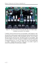
Figure 31. Top view of the finished amp PCB with the output stage
transistors secured to the heatsink.
Carefully maneuver the PCB onto the standoffs on the heatsink, mak-
ing sure the screws pass through the transistor holes while the ceramic
washers remain in position. Place and tighten the four 30-mm stand-
offs and the two M3 nuts to fix the PCB securely to the heatsink. Also
use M3 washers to fix the four power transistors and don’t forget the
insulating bushes for T17 and T18 (type IB 6 from Fischer Elektronik
or similar). Tighten the six screws. Place IC3 in its socket. Figure 31
shows the practically finished power amplifier.
Содержание Fortissimo-100
Страница 7: ...Elektor Fortissimo 100 Power Amplifier Kit 8 Figure 2 The resistors and small capacitors in the kit ...
Страница 10: ... 11 Figure 7 The mechanical parts in the kit Figure 8 The SK104 heatsinks in the kit 1 Kit Contents ...
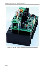
Страница 31: ...Elektor Fortissimo 100 Power Amplifier Kit 32 Figure 33 Left side view of the Fortissimo 100 Power Amplifier ...
Страница 32: ...15 Final Assembly 33 Figure 34 Right side view of the Fortissimo 100 amplifier ...
Страница 48: ...23 Schematics and PCB Layouts 49 Figure 46 Bottom side copper layout for both PCBs 210364 1 v1 1 ...


