18 – The SMPS800RE Power Supply
●
37
more temperature dependent, though. You can use a 40 VDC power
supply for the collector voltage if available. 6k8 should be a little lower
(6k2) if you want to measure at 2.4 mA.
For the second differential stages, a few things need to be adapted.
The current per transistor must be increased to approximately 9 mA
(the values between parentheses). Select the common-emitter resis-
tor and negative supply voltage to set a total current of 18 mA.
When using the differential test circuit, keep one transistor in place in
the test circuit and change the other one with all the others. Again,
turn off the power supply each time when removing or inserting an-
other transistor! Measure and make a note of each offset per newly in-
serted transistor. Wait for the offset to settle to a stable reading. Place
all available transistors in a piece of anti-static foam and use pliers to
swap them on the breadboard. If not, the body heat of your fingers
will seriously affect the time it takes for the reading to stabilize. Maybe
a better transistor pair can be found by choosing two transistors with
closer or — ideally — identical offsets. The best pair should be used for
the first differential amplifier at the input, i.e., the NPN pair and the
PNP pair, and the next best combination goes in the second stages.
18 – The SMPS800RE Power Supply
Figure 38. The Fortissimo-100 amplifier experimentally
connected to the SMPS800RE power supply.
Содержание Fortissimo-100
Страница 7: ...Elektor Fortissimo 100 Power Amplifier Kit 8 Figure 2 The resistors and small capacitors in the kit ...
Страница 10: ... 11 Figure 7 The mechanical parts in the kit Figure 8 The SK104 heatsinks in the kit 1 Kit Contents ...
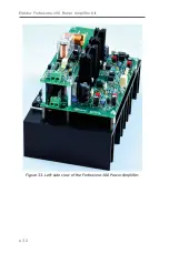
Страница 31: ...Elektor Fortissimo 100 Power Amplifier Kit 32 Figure 33 Left side view of the Fortissimo 100 Power Amplifier ...
Страница 32: ...15 Final Assembly 33 Figure 34 Right side view of the Fortissimo 100 amplifier ...
Страница 48: ...23 Schematics and PCB Layouts 49 Figure 46 Bottom side copper layout for both PCBs 210364 1 v1 1 ...


