


14 – The Output-Stage Transistors
●
27
14 – The Output-Stage Transistors
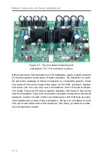
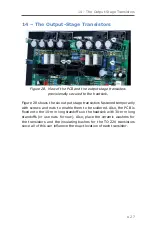
Figure 28. View of the PCB and the output stage transistors
provisionally secured to the heatsink.
Figure 28 shows the six output stage transistors fastened temporarily
with screws and nuts to enable them to be soldered. Also, the PCB is
fixed onto the 10-mm long standoffs on the heatsink with 30-mm long
standoffs (or use nuts for now). Also, place the ceramic washers for
the transistors and the insulating bushes for the TO-220 transistors
since all of this can influence the exact location of each transistor.
Содержание Fortissimo-100
Страница 7: ...Elektor Fortissimo 100 Power Amplifier Kit 8 Figure 2 The resistors and small capacitors in the kit ...
Страница 10: ... 11 Figure 7 The mechanical parts in the kit Figure 8 The SK104 heatsinks in the kit 1 Kit Contents ...
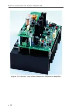
Страница 31: ...Elektor Fortissimo 100 Power Amplifier Kit 32 Figure 33 Left side view of the Fortissimo 100 Power Amplifier ...
Страница 32: ...15 Final Assembly 33 Figure 34 Right side view of the Fortissimo 100 amplifier ...
Страница 48: ...23 Schematics and PCB Layouts 49 Figure 46 Bottom side copper layout for both PCBs 210364 1 v1 1 ...


