


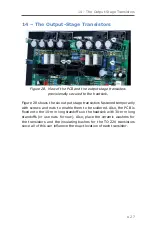


14 – The Output-Stage Transistors
●
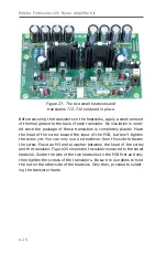
29
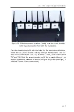
Figure 30. Slide the ceramic washers (pads) over the screw threads
before positioning the PCB with the transistors.
Place the heatsink upright with the holes for the transistors at the top.
Insert the six (black) screws halfway through the heatsink. The 16-
mm, black screws take T19…T22, and the 12-mm, black screws take
T17 and T18. Slide the ceramic washers with the greased side over the
screws against the heatsink as shown in Figure 30 (in the prototype, 6
off black 16-mm screws were used).
Содержание Fortissimo-100
Страница 7: ...Elektor Fortissimo 100 Power Amplifier Kit 8 Figure 2 The resistors and small capacitors in the kit ...
Страница 10: ... 11 Figure 7 The mechanical parts in the kit Figure 8 The SK104 heatsinks in the kit 1 Kit Contents ...
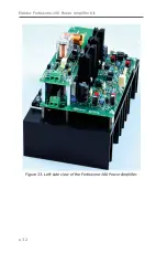
Страница 31: ...Elektor Fortissimo 100 Power Amplifier Kit 32 Figure 33 Left side view of the Fortissimo 100 Power Amplifier ...
Страница 32: ...15 Final Assembly 33 Figure 34 Right side view of the Fortissimo 100 amplifier ...
Страница 48: ...23 Schematics and PCB Layouts 49 Figure 46 Bottom side copper layout for both PCBs 210364 1 v1 1 ...


