


Elektor Fortissimo-100 Power Amplifier Kit
●
26
Figure 27. The two small heatsinks and
transistors T13…T16 soldered in place.
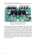
Before securing the transistors on the heatsinks, apply a small amount
of thermal grease to the back of each transistor. No insulation is need-
ed since the package of these transistors is completely plastic. Place
the head of the screw toward the input of the PCB, but don’t tighten
the screw yet. You can only use a screwdriver from this side to fasten
the screw. Place an M3 metal washer between the head of the screw
and the transistor. Figure 26 shows the transistors secured to the small
heatsink. Solder the pins of the two heatsinks to the PCB first and only
then tighten the screws of the transistors. Be sure to use pliers to hold
the nut on the other side of the heatsink. Only then, proceed to solder-
ing the transistor leads.
Содержание Fortissimo-100
Страница 7: ...Elektor Fortissimo 100 Power Amplifier Kit 8 Figure 2 The resistors and small capacitors in the kit ...
Страница 10: ... 11 Figure 7 The mechanical parts in the kit Figure 8 The SK104 heatsinks in the kit 1 Kit Contents ...
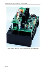
Страница 31: ...Elektor Fortissimo 100 Power Amplifier Kit 32 Figure 33 Left side view of the Fortissimo 100 Power Amplifier ...
Страница 32: ...15 Final Assembly 33 Figure 34 Right side view of the Fortissimo 100 amplifier ...
Страница 48: ...23 Schematics and PCB Layouts 49 Figure 46 Bottom side copper layout for both PCBs 210364 1 v1 1 ...


