Elektor Fortissimo-100 Power Amplifier Kit
●
42
K3,K4 (=K6,K7) + 4 for 2nd PCB = metal standoff, 30 mm, M3,
male-female (so 6 in total)
K8,K9 = Faston PCB, hole 3.3 mm, tab 6.35mm x 0.81mm
(42822-2 Amp/TE Connectivity or similar)
RE1 = Relay 16 A /250 VAC/30 VDC, G2R-1-E 48DC Omron
4 x M3 screw, 16 mm, black (T19/T20/T21/T22 to heatsink,
839672 Toolcraft)
8 x M3 screw, 12 mm, black (standoff PCB/T17/T18 to heatsink,
M312 PRSTMCB100- TR Fastenings)
4 x M3 screw, 8 mm (fasten 2 LSP standoffs and 2 Faston tabs)
18 x M3 nut
8 x M3 washer, plain, steel
6 x metal standoff, 10 mm, M3, male-female (PCB to heatsink)
HS1,HS2 = Heatsink, 9 °C/W, H 50.8 mm, SK 104 50,8 ST Fischer
Elektronik
T17-T22 = Heatsink, 0.6 °C/W, 100x180x48mm, SK53-100-SA
Fischer Elektronik
T19,T20,T21,T22 = Ceramic thermal pad, 23 x 20 mm x 2 mm
(SL-012-AL20 Silfox)
T17,T18 = Ceramic thermal pad, 18 x 12 x 1.5 mm
(SL-019-AL15, Silfox)
T17,T18 = Insulating bushing, TO-220 (IB 6, Fischer Elektronik)
IC3 = DIP-8 IC socket
Figure 40. Detail: 1-watt resistors R18 and R38 —
notice the size of R38.
The photo shows two different 1-watt resistors. Because of current
component shortages, some resistors and capacitors in the kit may
come from different series and manufacturers than mentioned in the
BOM and shown in the photos.
Содержание Fortissimo-100
Страница 7: ...Elektor Fortissimo 100 Power Amplifier Kit 8 Figure 2 The resistors and small capacitors in the kit ...
Страница 10: ... 11 Figure 7 The mechanical parts in the kit Figure 8 The SK104 heatsinks in the kit 1 Kit Contents ...
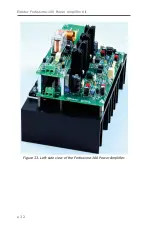
Страница 31: ...Elektor Fortissimo 100 Power Amplifier Kit 32 Figure 33 Left side view of the Fortissimo 100 Power Amplifier ...
Страница 32: ...15 Final Assembly 33 Figure 34 Right side view of the Fortissimo 100 amplifier ...
Страница 48: ...23 Schematics and PCB Layouts 49 Figure 46 Bottom side copper layout for both PCBs 210364 1 v1 1 ...


