Elektor Fortissimo-100 Power Amplifier Kit
●
24
Figure 24. Each of the two 30-mm standoffs is secured with an
8-mm M3 cheese head screw.
The two metal standoffs that connect the amplifier output lines of the
main PCB to the smaller PCB above it can now be fitted and secured
with an 8-mm long M3 cheese head screw.
13 – Transistors T13…T16 and the Small
Heatsinks
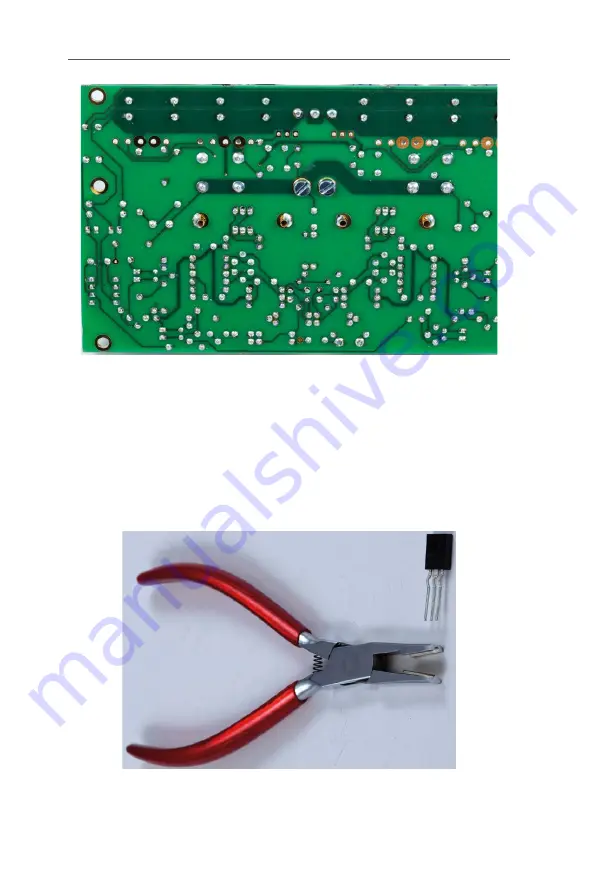
Figure 25. Special pliers and an example of the
“thermal relief” bend in the leads needed for T13…T16.
Содержание Fortissimo-100
Страница 7: ...Elektor Fortissimo 100 Power Amplifier Kit 8 Figure 2 The resistors and small capacitors in the kit ...
Страница 10: ... 11 Figure 7 The mechanical parts in the kit Figure 8 The SK104 heatsinks in the kit 1 Kit Contents ...
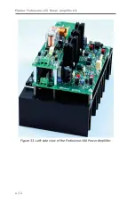
Страница 31: ...Elektor Fortissimo 100 Power Amplifier Kit 32 Figure 33 Left side view of the Fortissimo 100 Power Amplifier ...
Страница 32: ...15 Final Assembly 33 Figure 34 Right side view of the Fortissimo 100 amplifier ...
Страница 48: ...23 Schematics and PCB Layouts 49 Figure 46 Bottom side copper layout for both PCBs 210364 1 v1 1 ...


