Elektor Fortissimo-100 Power Amplifier Kit
●
28
Figure 29. The output stage transistors are soldered, and thermal
grease is applied to their backs.
As a minimum, solder the two leads at either side of each large power
transistor without melting any plastic of various capacitors. Do more
leads if possible. A longer soldering tip is recommended. All leads of
T17 and T18 can be soldered from the top. When this is done, remove
the screws that hold the transistors first and then the standoffs that
hold the PCB. Carefully take the PCB off the heatsink and make sure
not to bend the transistors. Now, the transistors are attached to the
PCB at their final position. Solder the rest of the leads from the bottom
side. 2-way screw terminal block K2 was not soldered yet to give better
access to the leads of T19 and this should be done now. Then apply a
very thin layer of thermal grease to the back of the six transistors and
one side of each ceramic washer that is placed against the heatsink.
Содержание Fortissimo-100
Страница 7: ...Elektor Fortissimo 100 Power Amplifier Kit 8 Figure 2 The resistors and small capacitors in the kit ...
Страница 10: ... 11 Figure 7 The mechanical parts in the kit Figure 8 The SK104 heatsinks in the kit 1 Kit Contents ...
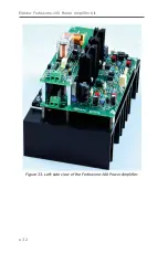
Страница 31: ...Elektor Fortissimo 100 Power Amplifier Kit 32 Figure 33 Left side view of the Fortissimo 100 Power Amplifier ...
Страница 32: ...15 Final Assembly 33 Figure 34 Right side view of the Fortissimo 100 amplifier ...
Страница 48: ...23 Schematics and PCB Layouts 49 Figure 46 Bottom side copper layout for both PCBs 210364 1 v1 1 ...


