960E
Installation Manual
ECI Telecom Ltd. Proprietary
4
1.2.2. Central
Connection
Panel
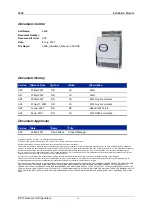
Figure 5.
Central Connection Panel
The Central Connection Panel, located at the top of the 960E, contains connectors for line
connections, power source, external alarms, NI card uplinks, clock reference, and local
craft.
Table 1: Front Panel Connectors
Label
Type
Function
Mates with…
+A –A +B –B
POWER
D-type 5W5
male
Provides input for DC power source.
To support redundancy, each 960E
supports dual A and B power feeds.
Power Cable (3 Meters)
POTS
DB-78 Male
connector
Accommodates up to 32 copper pairs
to the POTS
DB-78 Female
NI-A
NI-B
D-type 44 pin
male
Enables uplink copper connection to
NI cards
Copper uplink lines
LINES
DB-78 Male
connector
Accommodates up to 32 copper pairs
to the subscriber lines
DB-78 Female
RS-232
RS-232
Female DB-9
connector
Enables on-site technician to connect
a portable PC to the 960E Craft port
over RS-232.
RS-232 Male DB-9
ALARMS DB-37
Male
Alarm connector for input alarms,
input clocks, output alarms EU and
output alarms NA
DB-26 Female
ETHERNET
A, B
RJ-45 Female
For Ethernet 10/100/1000BaseT
service.
RJ-45 Male
ETH CLK
D-type 44 pin
male
Enables extracting clock from
Ethernet packets (requires additional
module on CCP)
Clock extractor module
EXT CLK
RJ-45 Female
2 Mbps clock in and out for uplink
copper synchronization
RJ-45 Male
RS 485
RJ-45 Female
Enable remote control for external
devices
RJ-45 Male
ETH-8
ETH-9
RJ-45 Female
For Ethernet 10/100BaseT service.
RJ-45 Male


