960E
Installation Manual
ECI Telecom Ltd. Proprietary
45
B.4.3. Ethernet 10/100/1000BaseT
Out-of-band management is conducted through a 100Base-T RJ45 connector Ethernet
port. Port A connects to IPNI A and port B connects to IPNI B.
Ethernet connector marked ‘A’ connects to the default IPNI card in slot A.
Ethernet connector marked ‘B’ connects to the alternate IPNI card in slot B. The RJ-45
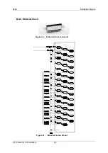
Ethernet connection is used for management and monitoring. The pin-out is described in
the following table.
Figure 35.
CP Ethernet A and B RJ-45 Connectors
Table 6:
Ethernet RJ-45 Pin out
Pin
Signal
1 ETH
TX
H
2 ETH
TX
L
3
ETH RX H
4 A_ETH_TXH
5 A_ETH_TXL
6
ETH RX L
7 A_ETH_RXH
8 A_ETH_RXL
B.4.4. RS-485 Connector
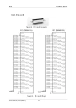
The RS-485 connector is for external control, such as automatic MDF.
The RS-485 connector pin-outs are shown in the following table.
Table 7:
RS-485 Connector Pin Assignments
Pin
Signal
Connector
1 485TXH
2 485TXH
3 485TXH
4 NC
5 NC
6 485TXH
7 GND
8 GND
9 GND
1
2
3
4
5
6
7
8
9
9_pin_D


