960E
Installation Manual
ECI Telecom Ltd. Proprietary
15
4.3. Card
Installation
Warning:
The technician installing Line/Network/Fan cards should wear an ESD
(Electrostatic Discharge) wrist strap during installation.
4.3.1.
Card Installation Procedure
¾
To install the Line/NI/ card:
1. Remove the Line/NI card from its anti-static package. Take care not to touch the
surface of the line card.
2. Raise the locking levers on both ends of the card.
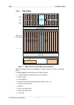
3. Align the Line/NI/ splitter card with the guide rails in the 960E frame and push the
card along the slide rail into the slot with even force until it meets the connection
socket on the backplane.
4. Press down on the locking levers on both ends of the card to plug the card into the
backplane and complete the installation.
5. Repeat these instructions to install the remaining cards.
Warning:
The NI cards can be inserted only in the dedicated NI slots. NI cards
are installed in the 16 and 17 (A and B) slots. For only a single NI card, insert the
card into slot 17.
¾
To install the GPLT 4 card:
1. Remove the GPLT 4 card from its anti-static package. Take care not to touch the
surface of the line card.
2. Raise the locking levers on both ends of the card.
3. Align the GPLT 4 card with the guide rails in the 960E frame and push the card
along the slide rail into the slot with even force until it meets the connection socket
on the backplane.
4. Press down on the locking levers on both ends of the card to plug the card into the
backplane and complete the installation.
5. Repeat these instructions to install the remaining cards.
¾
To install the CFU card:
1. Remove the CFU card from its anti-static package. Take care not to touch the
surface of the power supply card.
2. Raise the locking lever on the card.
3. Align the CFU card with the guide rails in the 960E frame and push the card along
the slide rail into the slot with even force until it meets the connection socket on
the backplane.


