960E
Installation Manual
ECI Telecom Ltd. Proprietary
33
B.
Cables and Connectors
B.1.
Alarm and Clock
B.1.1. Clock Reference Connector
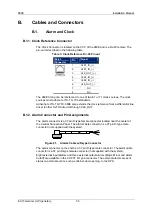
The Clock Connector is located on the CCP of the 960E and is a RJ-45 female. The
pin-out is described in the following table.
Table 3: Clock Reference RJ-45 Pin out
RJ-45
Connector
Pin
Signal
1 CL)
2 CLK1_IN_(-)
3 CL)
4 CL)
5 CLK2_IN_(-)
6 CLK_OUT_(-)
7 NC
8 NC
The 960E timing can be referenced to one of two E1 or T1 clock sources. The clock
sources must adhere to ITU-T G.703 standards.
Adhering to ITU-T G703, 960E also extends the clock reference from a differential line
driver to other Hi-FOCuS units through CLK_OUT.
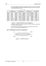
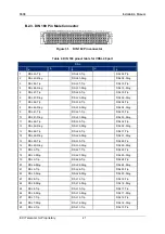
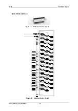
B.1.2. Alarm Connector and Pin Assignments
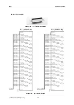
The alarm connector is a 37-pin D-type female connector located near the center of
the Central Connection Panel. The alarm cable connector is a 37 pin D-type male
connector (not supplied with the system).
Figure 21.
Alarms Cable w/D-type Connector
The alarm connector on the shelf is a 37 pin D-type male connector. The alarm cable
connector is a 37 pin D-type female connector (not supplied with the system).
Eight external input alarms and three external output alarms (Major, Minor and Alarm
Cutoff) are available in the CCP 37 D-Type connector. The external alarms are sent
status on external events, such as cabinet door opening, to the OPS.

