28
InStALLAtIon And opErAtIon mAnuAL
25-13741-E
January 2020 www.eaton.com
10. Installation
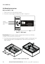
5. Knockouts are provided at the edges of the unit to support wall mounting and at
rear of the unit to support flush mounting. Double tag knockouts are provided for
easy removal. Remove knockouts as required by the application.
6. Mount the unit on the wall.
Figure 23. Wall mounting points
7. Wiring: Wire the unit. For details refer to leaflet provided with the unit or
section 10.5
Connection
Status
Instructions
Speaker
In place in received unit
Earth Connection
In place in received unit.
To be reconnected by installer
Loop In
To be done by installer
Refer Figure 34
Loop Out
To be done by installer
Refer Figure 34
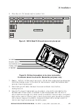
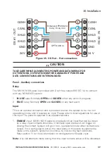
Figure 24. type B oS pCB connector placement
OS TYPE B PCB
SPEAKER
CANH
OS OUT (PORT B)
1
2
3
4
5
6
CANL
SHL
D
SHL
D
GND
24V
CANH
OS IN (PORT A)
1
2
3
4
5
6
CANL
SHL
D
SHL
D
GND
24V
Mounting Holes
142.8mm
54.5mm
Содержание VoCALL 16
Страница 96: ...96 Installation and operation manual 25 13741 E January 2020 www eaton com 17 Log Viewer...
Страница 103: ...103 Installation and operation manual 25 13741 E January 2020 www eaton com 18 Webserver...
Страница 115: ...115 Installation and operation manual 25 13741 E January 2020 www eaton com Notes...


