Sonix 350-d Technical Manual
3.4.2 Amp Bus
The Amp bus is connected to a Sonix 2Mx central
controller and other 350-d amplifiers. A working
Amp Bus connection is required to enable the 350-d
functionality. Each CAT6A cable provides bidirectional
data and audio transmission between the 2Mx and 350-
d. In the event of either one of those cables becoming
disconnected or otherwise broken both data and audio
has a redundant path, ensuring the system will continue
to operate without any loss of functionality (a connection
fault is raised by the system).
ote:
N
It is recommended that within the PA/GA cabinet these cables do
not exceed 25m in length. Please consult Eaton if greater distances are
required.
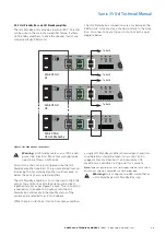
For single amplifier unit connection to the Sonix 2Mx module
is made with a cable from the 350-d’s top Amp Bus port (see
Figure 2) plugged into the top port of the 2Mx’s Amp Bus.
With a second cable from the 350-d’s Amp Bus bottom port
plugged into the bottom port of the 2Mx’s Amp Bus, closing
the loop.
A simple connection diagram is presented on an illustration
below:
Hmi Bus
Amp Bus
Hmi Bus
I/O Bus
Sonix 2Mx
COMPLIANT
Hot Standby
Amp Bus
EOL-8 Bus
Fuse
Danger - Hazardous Voltages Present!
COMPLIANT
Amp
Fault
O/P
N/C
com
PSU
Fault
O/P
N/C
com
48 V
DC
I/P
+ -
Sonix 350-d
Hmi Bus
Amp Bus
Hmi Bus
I/O Bus
Sonix 2Mx
COMPLIANT
Hot Standby
Amp Bus
EOL-8 Bus
Fuse
Danger - Hazardous Voltages Present!
COMPLIANT
Amp
Fault
O/P
N/C
com
PSU
Fault
O/P
N/C
com
48 V
DC
I/P
+ -
Sonix 350-d
#1
Hot Standby
Amp Bus
EOL-8 Bus
Fuse
Danger - Hazardous Voltages Present!
COMPLIANT
Amp
Fault
O/P
N/C
com
PSU
Fault
O/P
N/C
com
48 V
DC
I/P
+ -
Sonix 350-d
#2
Hot Standby
Amp Bus
EOL-8 Bus
Fuse
Danger - Hazardous Voltages Present!
COMPLIANT
Amp
Fault
O/P
N/C
com
PSU
Fault
O/P
N/C
com
48 V
DC
I/P
+ -
Sonix 350-d
#n
Figure 4. Connecting single 350-d to 2Mx module. View of rear of the units.
When connecting more than one Sonix 350-d unit, the top port
of the 2Mx is connected to the top port of the first 350-d unit
while the bottom port of the 2Mx is connected to the bottom
port of the last 350-d unit in the chain. For all remaining 350-d
units in the chain, the bottom port of one unit is connected to
the top port of the next unit in a chain, as per diagram below:
Hmi Bus
Amp Bus
Hmi Bus
I/O Bus
Sonix 2Mx
COMPLIANT
Hot Standby
Amp Bus
EOL-8 Bus
Fuse
Danger - Hazardous Voltages Present!
COMPLIANT
Amp
Fault
O/P
N/C
com
PSU
Fault
O/P
N/C
com
48 V
DC
I/P
+ -
Sonix 350-d
Hmi Bus
Amp Bus
Hmi Bus
I/O Bus
Sonix 2Mx
COMPLIANT
Hot Standby
Amp Bus
EOL-8 Bus
Fuse
Danger - Hazardous Voltages Present!
COMPLIANT
Amp
Fault
O/P
N/C
com
PSU
Fault
O/P
N/C
com
48 V
DC
I/P
+ -
Sonix 350-d
#1
Hot Standby
Amp Bus
EOL-8 Bus
Fuse
Danger - Hazardous Voltages Present!
COMPLIANT
Amp
Fault
O/P
N/C
com
PSU
Fault
O/P
N/C
com
48 V
DC
I/P
+ -
Sonix 350-d
#2
Hot Standby
Amp Bus
EOL-8 Bus
Fuse
Danger - Hazardous Voltages Present!
COMPLIANT
Amp
Fault
O/P
N/C
com
PSU
Fault
O/P
N/C
com
48 V
DC
I/P
+ -
Sonix 350-d
#n
Figure 5. Connecting multiple 350-d units to 2Mx module
ote:
N
The maximum number of units to be connected in a chain is 32,
if this is insufficient please contact your local Eaton representative to
discuss your requirements.
In the special case of PA/GA system being configured
as an N+1 System, additional equipment in the form of
N+1 Tap Board should be used. For details please refer
to 2Mx Product Manual.
11
SONIX 350-D TECHNICAL MANUAL
TM367 / A May 2022 www.eaton.com

