


188
Chapter 7- Multi-purpose application
POWERXL DM1 SERIES VARIABLE FREQUENCY DRIVES
MN040049EN
—September 2021 www.eaton.com
Table 61. Motor control (Cont.).
P5.1 - Basic settings.
P5.1.1
ab
Motor control mode
ID 287
Minimum value:
N.A.
Maximum value:
N.A.
Default value:
0
Options:
0 = Frequency control - Output frequency is controlled directly by the frequency reference.
1 = Speed control - Output frequency is controlled by giving a frequency reference to it with slip compensation.
2 = Open loop vector control - Similar to the standard speed control mode, higher performance slip calculation requires running a motor
identification.
3 = PM control 1 - PM motor control mode 1, used for SPM (surface mounted permanent magnet) and it also can be used for IPM.
4 = PM control 2 - PM motor control mode 2, used for IPM (internally mounted permanent magnet) and it can not be used for SPM.
Description:
Selects the motor control mode
.
P5.1.2
a
Current limit
ID 107
Minimum value:
DriveNomCurrCT*1/10 A
Maximum value:
DriveNomCurrCT*2 A
Default value:
DriveNomCurrCT*3/2 A
Description:
This parameter determines the maximum output current allowed from the drive. The parameter value range differs from size to size.
Once the motor current hits this level, it goes into the current limiter controller and tries to limit the output current.
P5.1.3
ab
V/Hz optimization
ID 109
Minimum value:
N.A.
Maximum value:
N.A.
Default value:
0
Options:
0 = Disable torque boost function.
1 = Enable torque boost function.
Description:
Automatic torque boost - the voltage to the motor increases automatically, which assists the motor to produce sufficient torque to start
and run at low frequencies with high loads.
P5.1.4
ab
V/Hz ratio
ID 108
Minimum value:
N.A.
Maximum value:
N.A.
Default value:
0
Options:
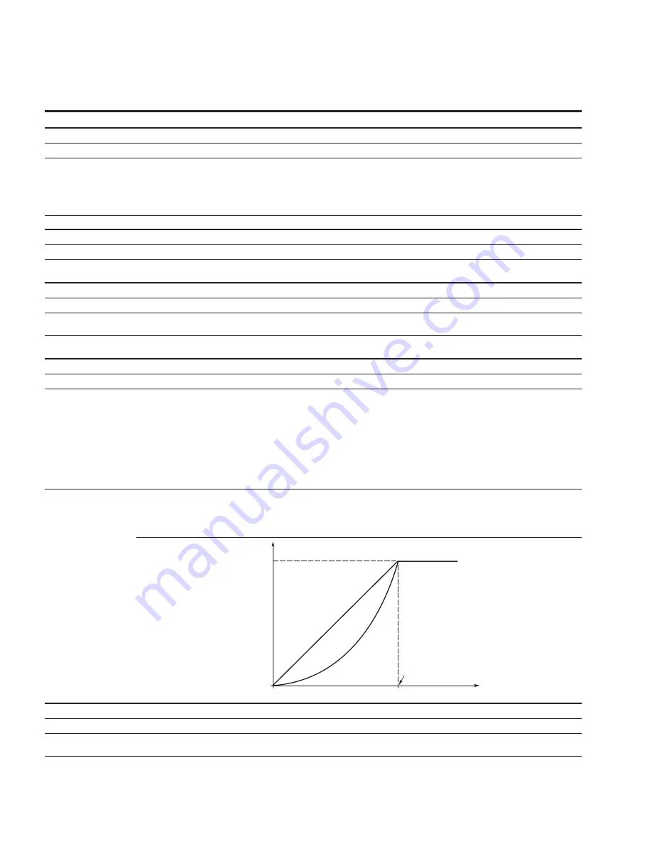
0 = Linear - the voltage of the motor changes linearly with the frequency in the constant flux area from 0 Hz to the field weakening point
where the nominal voltage is supplied. A linear V/Hz ratio should be used in constant torque applications.
1 = Squared - the voltage of the motor changes following a squared curve with the frequency in the area from 0 Hz to the field
weakening point where the nominal voltage is supplied. The motor runs under magnetized below the field weakening point and
produces less torque and electromechanical noise. A squared V/Hz ratio can be used in applications where the torque demand of
the load is proportional to the square of the speed.
2 = Programmable V/Hz curve - the V/Hz curve can be programmed with three different points. These points are the 0 frequency
voltage, midpoint and weakening point. A programmable V/Hz curve can be used if the other settings do not satisfy the needs of
the application.
3 = Linear with flux optimization - the drive starts to search for the minimum motor current in order to save energy. This mode is called
Eaton’s Active Energy Control which will reduce the voltage and current but still maintain the desired speed.
Description:
Selects the V/Hz ratio.
0 = Linear;
1 = Squared;
2 = Programmable; or
3 = flux optimization.
U[V]
f [Hz]
Linear
Squared
Un
Voltage
at FWP
Default: Nominal
Voltage of the Motor
Field Weakening
Point
Default: Nominal
Frequency of the
Motor
0 = Linear and 1 = Squared.
P5.1.5
ab
Field weakening point
ID 289
Minimum value:
8.00 Hz
Maximum value:
400.00 Hz
Default value:
FieldWeakPointMFG Hz
Description:
The field weakening point is the frequency at which the output voltage reaches the set maximum value. This value is usually determined
by the motor nameplate value.
.