6 Parameter structure
6.6 Parameter
DC1-S…20…, DC1-S…OE1 Variable Frequency Drives
05/21 MN040058EN
www.eaton.com
149
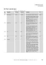
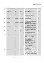
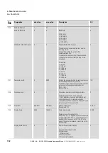
P-19
RO1 upper Limit
0.00 %
200.00 %
Switching ON threshold of relay RO1
with P-18 = 4, …, 7, 10
100.00 %
P-20
Preset Speed 1
Min Frequency
Max Frequency
Preset Fixed Frequency 1
Value can be adjusted between f-min and f-max.
Selection via a digital control signal.
If P-09 is changed, the value is reset to default.
15.0 hz
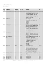
P-21
Preset Speed 2
Min Frequency
Max Frequency
Preset Fixed Frequency 2
Value can be adjusted between f-min and f-max.
Selection via a digital control signal.
If P-09 is changed, the value is reset to default.
0.0 Hz
P-22
Preset Speed 3
Min Frequency
Max Frequency
Preset Fixed Frequency 3
Value can be adjusted between f-min and f-max.
Selection via a digital control signal.
If P-09 is changed, the value is reset to default.
0.0 Hz
P-23
Preset Speed 4
Min Frequency
Max Frequency
Preset Fixed Frequency 4
Value can be adjusted between f-min and f-max.
Selection via a digital control signal.
If P-09 is changed, the value is reset to default.
0.0 Hz
P-24
t-QuickDec
0.00 s
600.0 s
Quick Stop Ramp
In default the second deceleration ramp is
activated by applying voltage to DI1 and DI2
(terminals 2 and 3) at the same time.
0.00 s
P-25
AO1 Function
0
12
Select Signal to show on the analog output
P-25 = 0, …, 7, 10, 11 = digital output
0: RUN, enable (FWD/REV)
1: READY, DC1...E1 ready for operation
2: Speed = speed reference value
3: Fault (DC1...E1 not ready)
4: Speed
≧
RO1 Upper Limit (P-19)
5: Motor current
≧
RO1 Upper Limit (P-19)
6: Speed < RO1 Upper Limit (P-19)
7: Motor current < RO1 Upper Limit (P-19)
10: Drive not enabled
11: Speed not at reference value
P-25 = 8, 9, 12 = analog output
8: Output Frequency (0 - 100 % f-max (P-01))
9: Motor current (0 - 200 % Motor Nom Current
(P-08))
12: Motor power
8
P-26
f-SkipBand1
0.0 Hz
Max Frequency
Skip frequency band width
Defines the frequency range around f-Skip1 in
which the drive doesn’t work in steady-state to
avoid mechanical resonances in the application.
During acceleration and deceleration this range is
passed through by using the ramps set with P-03
and P-04.
0.0 Hz
Para-
meter
Designation
min. value
max. value
Description
DS
Содержание DC1-S1011NB-A20CE1 1
Страница 4: ......
Страница 124: ...5 Operation 5 7 Handling the keypad 120 DC1 S 20 DC1 S OE1 Variable Frequency Drives 05 21 MN040058EN www eaton com...
Страница 160: ...6 Parameter structure 6 7 Fault messages 156 DC1 S 20 DC1 S OE1 Variable Frequency Drives 05 21 MN040058EN www eaton com...
Страница 170: ...7 Technical Data 7 3 Dimensions 166 DC1 S 20 DC1 S OE1 Variable Frequency Drives 05 21 MN040058EN www eaton com...


