5 Operation
5.5 Commissioning with control signal terminals (default settings)
DC1-S…20…, DC1-S…OE1 Variable Frequency Drives
05/21 MN040058EN
www.eaton.com
115
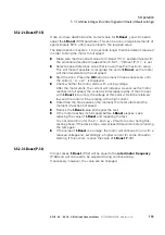
5.5.2.2 t-Boost (P-33)
Once you have determined the correct value for
V-Boost
, you will need to
adjust the
t-Boost
(P-33) parameter. This can be done in large increments of
approximately 50 % until you are close to the required value.
The ideal duration is approx. 1 to 2 seconds longer than the duration required
in order to bring the motor to full speed.
▶
Make sure that the correct value for V-Boost (P-11), as determined with
the procedure described in
section 5.5.2.1, “V-Boost (P-11)”, is set.
▶
Select a speed reference value that is lower than the maximum value.
This will make it possible to recognize the end of
t-Boost
, as the motor
will then decelerate to the set speed.
▶
Start the drive. Press the
OK
button as many times as necessary until
the current, “A…xxx”, is displayed.
▶
Check whether the motor starts with a rising voltage.
After the motor starts, the current will increase. As soon as the motor
reaches its full speed, the current will decrease rapidly. If the time set
with
t-Boost
is too long, the voltage at this point will still be relatively
low and the motor will be rotating with a high current.
▶
Determine the time between the moment the motor starts and the
moment it reaches full speed.
▶
Reduce the
t-Boost
value and repeat the test.
▶
If the motor reaches its full speed before
t-Boost
elapses, keep
reducing the value of
t-Boost
and repeating the test.
It is not uncommon for the
O-I
and
It.trp
faults to occur during this
testing phase. If the device trips, wait at least 30 seconds before running
the test again.
▶
If the value of
t-Boost
is too large, the motor will continue to run with a
reduced voltage and, accordingly, a higher current for some time after
starting. If this occurs, reduce the value of
t-Boost
(P-33).
5.5.2.3 f-Boost (P-32)
In most cases,
f-Boost
(P-32) will be equal to the
rated motor frequency
(P-09) and will not need to be adjusted during commissioning.
If necessary, however, the value can be changed.
Содержание DC1-S1011NB-A20CE1 1
Страница 4: ......
Страница 124: ...5 Operation 5 7 Handling the keypad 120 DC1 S 20 DC1 S OE1 Variable Frequency Drives 05 21 MN040058EN www eaton com...
Страница 160: ...6 Parameter structure 6 7 Fault messages 156 DC1 S 20 DC1 S OE1 Variable Frequency Drives 05 21 MN040058EN www eaton com...
Страница 170: ...7 Technical Data 7 3 Dimensions 166 DC1 S 20 DC1 S OE1 Variable Frequency Drives 05 21 MN040058EN www eaton com...


