5 Operation
5.7 Handling the keypad
118
DC1-S…20…, DC1-S…OE1 Variable Frequency Drives
05/21 MN040058EN
www.eaton.com
5.7 Handling the keypad
The keypad can be used to configure the DC1-S… variable frequency drive’s
parameters and monitor its operation.
5.7.1 Operating unit elements
The following figure shows the elements of the DC1-S… variable frequency
drive integrated operating unit.
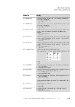
Figure 74: Operating unit view (example DC1-…-A20…)
→
Manual MN040022EN, “DC1 Variable Frequency Drives –
Parameter Manual,” goes over how to configure the individual
parameters.
Display (7-digital LEDs)
Push buttons
→
If you intend to use an external keypad and/or a parameter
copying stick with the DC1-…CE1 variable frequency drive,
please note that only models DX-KEY-LED
2
and DX-COM-STICK
2
will work.
DX-KEY-OLED can be used, but requires an update first.
→
The integrated keypad on DC1 devices and the (optional)
external DX-KEY-
LED2
keypad feature a six-digit 7-segment
LED display.
The optional DX-KEY-
OLED
keypad is a multi-language cleartext
display unit (OLED = Organic light-emitting diode).
It can be used in conjunction with DC1 variable frequency
drives. The buttons on both keypads work the exact same way.
The additional
Hand
and
Auto
buttons on the DX-KEY-OLED
keypad do not do anything in this case.
Содержание DC1-S1011NB-A20CE1 1
Страница 4: ......
Страница 124: ...5 Operation 5 7 Handling the keypad 120 DC1 S 20 DC1 S OE1 Variable Frequency Drives 05 21 MN040058EN www eaton com...
Страница 160: ...6 Parameter structure 6 7 Fault messages 156 DC1 S 20 DC1 S OE1 Variable Frequency Drives 05 21 MN040058EN www eaton com...
Страница 170: ...7 Technical Data 7 3 Dimensions 166 DC1 S 20 DC1 S OE1 Variable Frequency Drives 05 21 MN040058EN www eaton com...


