3 Installation
3.3 Mounting
52
DC1-S…20…, DC1-S…OE1 Variable Frequency Drives
05/21 MN040058EN
www.eaton.com
▶
First fit the screws at the specified positions, mount the variable
frequency drive and then fully tighten all screws.
Table 4:
Installation dimensions, screws, tightening torques
3.3.3.2 Fixing on a mounting rail
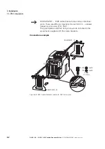
As an alternative to screw fixing, DC1-S… variable frequency drives with
sizes FS1 and FS2 and a degree of protection of IP20 can also be mounted
on a mounting rail as per IEC/EN 60715.
Figure 25: Mounting rail conforming with IEC/EN 60715
▶
To do this, place the variable frequency drive on the mounting rail from
above [1] and press it down until it snaps into place [2].
Frame size Degree of
protection
a1
b1
Screw
Tightening Torque
FS
IP
NEMA
mm
in
mm
in
Quantity
Size
Nm
lb-in
FS1
IP20
NEMA 0
50
1.97
170
6.69
4
M4
1
8.85
FS1
IP66
NEMA 4X
184.5
5.85
189
7.44
4
M4
1.2 - 1.5
10.62 - 13.27
FS2
IP20
NEMA 0
75
2.95
215
8.46
4
M4
1
8.85
FS2
IP66
NEMA 4X
176
6.93
200
7.87
4
M4
1.2 - 1.5
10.62 - 13.27
1 in = 1’’ = 25.4 mm; 1 mm = 0.0394 in
→
If you use EMC mounting adapters (DX-EMC-MNT-…), use a tall
mounting rail (15 mm) preferably.
→
If you use EMC mounting adapters (DX-EMC-MNT-…), use a tall
mounting rail (15 mm) preferably.
35
1
7.5
15
1.38”
0.04”
0.29”
0.59”
Содержание DC1-S1011NB-A20CE1 1
Страница 4: ......
Страница 124: ...5 Operation 5 7 Handling the keypad 120 DC1 S 20 DC1 S OE1 Variable Frequency Drives 05 21 MN040058EN www eaton com...
Страница 160: ...6 Parameter structure 6 7 Fault messages 156 DC1 S 20 DC1 S OE1 Variable Frequency Drives 05 21 MN040058EN www eaton com...
Страница 170: ...7 Technical Data 7 3 Dimensions 166 DC1 S 20 DC1 S OE1 Variable Frequency Drives 05 21 MN040058EN www eaton com...

