Easy-Start ES
Solid State Reduced Voltage Motor Starter
Cutler-Hammer
Instruction Manual
For Model Easy-Start ES Solid State Reduced Voltage Motor Starter
StockCheck.com
Страница 1: ...d State Reduced Voltage Motor Starter Easy Start ES Solid State Reduced Voltage Motor Starter Cutler Hammer Instruction Manual For Model Easy Start ES Solid State Reduced Voltage Motor Starter S t o c...
Страница 2: ...ARDING THE INFORMATION RECOMMENDATIONS AND DESCRIPTIONS CONTAINED HEREIN In no event will Cutler Hammer be responsible to the purchaser or used in contract in tort including negligence strict liabilit...
Страница 3: ...oduction 1 1 Installation 2 1 Pre Installation 2 3 Drawings 2 19 Specifications 2 45 Operation 3 1 Operation 3 2 Adjustments 3 2 DIP Switch Settings 3 3 Options 4 1 Available Options 4 2 Application N...
Страница 4: ...Hammer Transformer 2 29 2 11 Dimension and Installation Open Panel ES045 _EP ES070 _EP ES120 _EP 2 30 2 12 Dimension and Installation Open Panel Slim Line Motor Control Center ES070 _EC 2 31 2 13 Dime...
Страница 5: ...ooth Stop with By Pass Contactor 4 26 4 6 Smooth Stop S1 Option 4 27 4 7 Smooth Stop with Remote Maintained 2 Wire Contact 4 28 4 8 Jam DIP Switch Trip Point Settings 4 29 4 9 Jam Trip Time Curves 4 2...
Страница 6: ...h Ampere Settings ES045 3 4 3 3 Dip Switch Ampere Settings ES070 3 5 3 4 Dip Switch Ampere Settings ES120 3 5 3 5 Dip Switch Ampere Settings ES180 3 6 3 6 Dip Switch Ampere Settings ES250 3 6 3 7 Dip...
Страница 7: ...es to point out how to safely operate and troubleshoot your starter After you review this section you will Understand the meaning of the Safety Alert Symbol Danger Warning Caution and Notice safety st...
Страница 8: ...death Safety Danger Warning means that failure to follow this safety statement could result in serious personal injury or death This instruction manual should be used for proper installation operation...
Страница 9: ...ional conduit and enclosure grounding Danger There can be line voltage potential at the motor load terminals even with the starter in the off state This is due to the RC snubber network across the SCR...
Страница 10: ...uccessful installation thoroughly read and understand the material presented in each section before you attempt to install the drive If this is your first installation we suggest that you read each se...
Страница 11: ...ers are shown in italics Items in bold italics are important If you have any questions or comments please feel free to contact us We at Cutler Hammer are proud to have you as a customer and can assure...
Страница 12: ...Solid State Reduced Voltage Starter To ensure successful installation thoroughly read and understand the material presented in this section before you attempt to install the Starter If this is your f...
Страница 13: ...nstallation section of this Instruction Manual provides guidelines to consider before you install your drive Description Easy Start ES Model Designation Application Considerations Considerations for F...
Страница 14: ...at light loads and saves power Block Diagram Description Figure 2 1 System Schematic Figures 2 2 and 2 3 The line current is sensed by using three current transformers These AC signals are converted...
Страница 15: ...t 50 of nominal line voltage The amplifier also has a stability adjustment which can be used to handle difficult motor load applications It is marked STAB and is factory set to approximately midpoint...
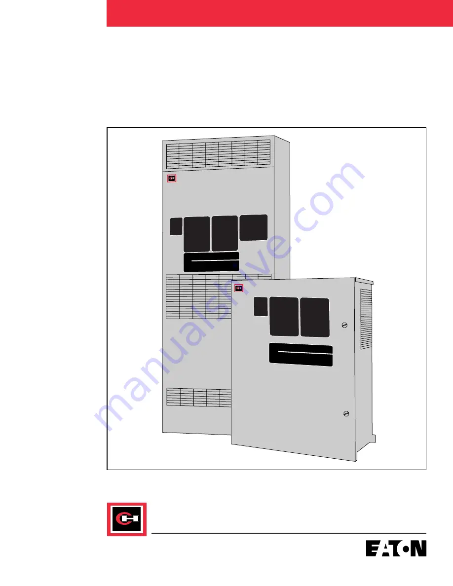
Страница 16: ...NL Large NEMA 1 070 EP Open Panel Isolated Heat Sink 120 NP Open Panel Non Isolated Heat Sink 180 Line Volts EC Open Panel Isolated Heat Sink 14 0 Wide 250 3 380 415V NC Open Panel Non Isolated Heat S...
Страница 17: ...r thru a properly gasketed cut out in the enclosure Approximately 50 watt loss is dissipated thru the heat sinks and the remaining 50 should be dissipated thru the remainder of the box surface not cou...
Страница 18: ...2 8 Application Considerations Frequent Starting Stopping The number of starts and stops depends upon many factors The most important ones are 1 Position of current limit potentiometer which can be a...
Страница 19: ...is started in either speed from complete stop The ramp soft start can be optimized for one speed only Going directly from low speed to high speed or high speed to low speed would not give smooth tran...
Страница 20: ...e of 500 current limit for 20 seconds The circuit breakers or protective devices used upstream should be sized so that they can handle the maximum current for 20 seconds or longer where extended start...
Страница 21: ...120 400 750 5 30 40 50 60 10 4 8 16 20 20 2 4 6 2 12 20 40 50 500 600 5 8 12 20 24 10 2 4 6 20 1 Starts Per Hour ES120 Table 2 3 Model Number ES180 Starts Per Hour Curr Starting Start Percent Off Tim...
Страница 22: ...00 5 24 35 50 60 10 12 16 20 30 20 4 8 12 15 2 30 50 70 100 500 1250 5 16 20 30 35 10 8 10 15 20 20 2 4 6 8 Starts Per Hour ES250 Table 2 5 Model Number ES260 Starts Per Hour Curr Starting Start Perce...
Страница 23: ...0 60 10 15 20 25 30 20 8 10 12 16 2 40 60 80 100 500 1800 5 20 30 40 50 10 10 15 20 25 20 4 8 10 12 Starts Per Hour ES360 Table 2 7 Model Number ES500 Starts Per Hour Curr Starting Start Percent Off T...
Страница 24: ...30 40 60 10 8 16 20 24 20 4 8 12 16 2 30 40 60 100 500 2800 5 12 20 30 40 10 4 8 12 16 20 2 4 6 Starts Per Hour ES560 Table 2 9 Model Number ES750 Starts Per Hour Curr Starting Start Percent Off Time...
Страница 25: ...t Current Time AC Amps Sec 0 10 20 30 2 150 200 300 360 250 2375 5 60 90 120 150 10 30 45 60 70 20 15 20 30 35 2 100 150 200 250 300 2850 5 40 60 80 100 10 20 30 40 50 20 10 15 20 25 2 60 100 120 150...
Страница 26: ...CPT connections After a trip the Easy Start ES must be reset by momentarily opening the 120 VAC on the logic board transformer T2 This is done by using a normally closed RESET pushbutton between TB1...
Страница 27: ...and H1 connections remain the same for all line voltages Wiring Practices Care should be taken to see that all interconnecting wiring and ground wiring is sized and installed in conformance with the...
Страница 28: ...U 2 Secondary Secondary Voltage Connection Connection Jumper Voltage 208 VAC H5 X3 H1 to H3 H2 to H5 110 VAC 380 VAC H4 X3 H2 to H3 120 VAC 415 VAC H5 X3 H2 to H3 120 VAC 460 VAC H4 X2 H2 to H3 115 VA...
Страница 29: ...ction Manual presents the following series of drawings Overload Characteristics Control Connection and Schematic Diagrams Outline dimensions and options for mounting each chassis Easy Start ES Instruc...
Страница 30: ...Drawings INSTALLATION 2 20 Easy ES 001 Block Diagram Figure 2 1 Easy Start ES Instruction Manual S t o c k C h e c k c o m...
Страница 31: ...Drawings INSTALLATION 2 21 Easy ES 002 System Schematic Hevi Duty Co Multi Volt Transformer Connections Figure 2 2 Easy Start ES Instruction Manual S t o c k C h e c k c o m...
Страница 32: ...Easy Start ES Instruction Manual Drawings INSTALLATION 2 22 230V 460V XF HR 208V 380V 415V XF HR Easy ES 003 System Schematic Cutler Hammer Transformer Connections Figure 2 3 S t o c k C h e c k c o m...
Страница 33: ...Easy Start ES Instruction Manual Drawings INSTALLATION 2 23 Easy ES 004 Logic Board Terminal Block TB1 Functions Figure 2 4 S t o c k C h e c k c o m...
Страница 34: ...24 Easy ES 005 Conversion factor multiply altitude in feet by 0 3048 to obtain altitude in meters 500 1500 2500 3500 0 1 0 2 0 3 0 4 0 5 0 6 0 7 0 8 0 9 1 0 Derate Factor Altitude Meters T 40 C Derate...
Страница 35: ...Easy Start ES Instruction Manual Drawings INSTALLATION 2 25 Easy ES 006 Momentary Contact Start Stop Pushbuttons Figure 2 6 S t o c k C h e c k c o m...
Страница 36: ...Easy Start ES Instruction Manual Drawings INSTALLATION 2 26 Easy ES 007 Hand Off Auto Selector Switch Figure 2 7 S t o c k C h e c k c o m...
Страница 37: ...Easy Start ES Instruction Manual Drawings INSTALLATION 2 27 Easy ES 008 Start Stop Pushbuttons With Hand Off Auto Selector Switch Figure 2 8 S t o c k C h e c k c o m...
Страница 38: ...Easy Start ES Instruction Manual Drawings INSTALLATION 2 28 Easy ES 009 Power Connections with Options Hevi Duty Co Multi Volt Transformer Figure 2 9 S t o c k C h e c k c o m...
Страница 39: ...Easy Start ES Instruction Manual Drawings INSTALLATION 2 29 Easy ES 010 Power Connections with Options Cutler Hammer Transformer Figure 2 10 S t o c k C h e c k c o m...
Страница 40: ...Easy Start ES Instruction Manual Drawings INSTALLATION 2 30 Easy ES 011 Dimension and Installation Open Panel ES045 _EP ES070 _EP ES120 _EP Figure 2 11 S t o c k C h e c k c o m...
Страница 41: ...D DEPTH IS 7 50 FIELD WIRING LUGS WIRE GAUGE RANGE LINE LOAD LUGS AWG 14 1 0 AWG 14 2 50 GROUND LUGS MODEL ES070 _EC WEIGHT LBS 2 00 3 75 13 69 6 25 0 00 13 25 10 13 219 DIA 3 88 75 0 0 50 3 42 4 50 9...
Страница 42: ...Easy Start ES Instruction Manual Drawings INSTALLATION 2 32 Easy ES 013 Dimension and Installation NEMA 12 Regular Enclosure ES045 _ER ES070 _ER Figure 2 13 S t o c k C h e c k c o m...
Страница 43: ...Easy Start ES Instruction Manual Drawings INSTALLATION 2 33 Easy ES 014 Dimension and Installation NEMA 12 Large Enclosure ES045 _EL ES070 _EL ES120 _EL Figure 2 14 S t o c k C h e c k c o m...
Страница 44: ...Start ES Instruction Manual Drawings INSTALLATION 2 34 Easy ES 015 Dimension and Installation Open Panel ES180 _NP ES260 _NP ES560 _NP ES250 _EP ES360 _EP ES500 _EP Figure 2 15 S t o c k C h e c k c...
Страница 45: ...DE PROPER COOLING 4 USER MUST PROVIDE LOAD LUGS 5 WHEN DAUGHTER BD OPTION IS USED DEPTH IS 7 50 FIELD WIRING LUGS WIRE GAUGE RANGE LINE LUGS AWG 6 250MCM AWG 14 2 60 GROUND LUGS MODEL ES120 _EC WEIGHT...
Страница 46: ...Easy Start ES Instruction Manual Drawings INSTALLATION 2 36 Easy ES 017 Dimension and Installation Open Panel Slim Line Motor Control Center ES180 _NC ES250 _NC Figure 2 17 S t o c k C h e c k c o m...
Страница 47: ...Easy Start ES Instruction Manual Drawings INSTALLATION 2 37 Easy ES 018 Dimension and Installation NEMA 1 Regular Enclosure ES180 _NR ES260 _NR ES560 _NR Figure 2 18 S t o c k C h e c k c o m...
Страница 48: ...Easy Start ES Instruction Manual Drawings INSTALLATION 2 38 Easy ES 019 Dimension and Installation NEMA 1 Large Enclosure ES180 _NL ES260 _NL ES560 _NL Figure 2 19 S t o c k C h e c k c o m...
Страница 49: ...Easy Start ES Instruction Manual Drawings INSTALLATION 2 39 Easy ES 020 Dimension and Installation Open Panel ES750 _NP Figure 2 20 S t o c k C h e c k c o m...
Страница 50: ...Easy Start ES Instruction Manual Drawings INSTALLATION 2 40 Easy ES 021 Dimension and Installation NEMA 1 Large Enclosure ES750 _NL Figure 2 21 S t o c k C h e c k c o m...
Страница 51: ...Easy Start ES Instruction Manual Drawings INSTALLATION 2 41 Easy ES 022 Dimension and Installation NEMA 12 Large Enclosure ES250 ES360 _EL Figure 2 22 S t o c k C h e c k c o m...
Страница 52: ...Easy Start ES Instruction Manual Drawings INSTALLATION 2 42 Easy ES 023 Dimension and Installation NEMA 12 Large Enclosure ES500 _EL Figure 2 23 S t o c k C h e c k c o m...
Страница 53: ...Easy Start ES Instruction Manual Drawings INSTALLATION 2 43 Easy ES 024 Dimension and Installation NEMA 1 ES950 _NL Figure 2 24 S t o c k C h e c k c o m...
Страница 54: ...Easy Start ES Instruction Manual Drawings INSTALLATION 2 44 Easy ES 025 Dimension and Installation Open Panel ES950 _NP Figure 2 25 S t o c k C h e c k c o m...
Страница 55: ...is part of the Installation section of this Instruction Manual presents the following specifications General Specifications Easy Start ES Instruction Manual 2 45 Specifications S t o c k C h e c k c o...
Страница 56: ...Voltage Rating Current Rating 45 260 Amp 360 950 Amp 208 230 460 Vac 1200 V 1500 V 380 415 Vac 1200 V 1500 V 460 500 575 Vac 1500 V 1500 V Transient Voltage Integral MOV Metal Oxide Varistor protects...
Страница 57: ...P switches set at time of installation See Section 3 Potentiometer Adjustments Current Trip 100 120 Clockwise rotation Current Limit 200500 increases value Voltage Current Ramp Selectable with switch...
Страница 58: ...ate reduced voltage motor starter After you review this section you will understand Operation of the Easy Start ES Motor Starter Adjustments Make sure you read understand and follow all of the Safety...
Страница 59: ...ever reach rated speed This may cause the electronic current over load to trip see Figure 3 1 Adjustments 1 Current Calibration DIP Switches DS1 DS2 work together as follows DS1 is active all the time...
Страница 60: ...1 0 497 0 454 0 408 0 379 0 356 0 333 0 1 1 0 0 656 0 589 0 542 0 496 0 448 0 416 0 392 0 367 0 1 1 1 0 709 0 640 0 589 0 540 0 489 0 455 0 430 0 403 1 0 0 0 0 743 0 672 0 620 0 570 0 516 0 481 0 454...
Страница 61: ...10 2 0 0 1 1 22 5 20 0 18 3 16 6 14 9 13 8 12 9 12 1 0 1 0 0 25 5 21 8 20 0 18 2 16 3 15 1 14 2 13 3 0 1 0 1 27 2 24 4 22 4 20 4 18 4 17 0 16 0 15 0 0 1 1 0 29 5 26 5 24 4 22 3 20 2 18 7 17 6 16 5 0 1...
Страница 62: ...45 1 42 3 40 1 37 8 1 1 0 1 65 4 59 9 55 8 51 8 47 4 44 5 42 2 39 8 1 1 1 0 67 7 62 1 58 0 53 9 49 4 46 4 44 1 41 6 1 1 1 1 70 0 64 4 60 2 56 1 51 5 48 4 46 1 43 5 DS1 DS2 POSITIONS 123 123 123 123 12...
Страница 63: ...0 143 6 133 2 121 9 114 3 108 4 102 4 1 1 1 0 174 1 159 8 149 2 138 6 127 1 119 4 113 3 107 0 1 1 1 1 180 0 165 6 154 8 144 2 132 5 124 6 118 4 112 0 DS1 DS2 POSITIONS 123 123 123 123 123 123 123 123...
Страница 64: ...42 8 222 4 207 4 192 3 176 1 165 1 156 6 147 9 1 1 1 0 251 4 230 8 215 5 200 1 183 5 172 5 163 7 154 6 1 1 1 1 260 0 239 2 223 6 208 3 191 4 179 9 171 1 161 7 DS1 DS2 POSITIONS 123 123 123 123 123 123...
Страница 65: ...1 1 0 1 467 0 427 8 398 8 369 9 338 6 317 6 301 2 284 4 1 1 1 0 483 5 443 9 414 4 384 9 353 0 331 7 314 8 297 4 1 1 1 1 500 0 460 0 430 0 400 5 368 0 346 0 329 0 311 0 DS1 DS2 POSITIONS 123 123 123 12...
Страница 66: ...0 1 1 0 1 700 5 641 7 598 2 554 8 507 9 476 3 451 8 426 6 1 1 1 0 725 3 665 8 621 5 577 3 529 4 497 5 472 1 446 0 1 1 1 1 750 0 690 0 645 0 600 8 552 0 519 0 493 5 466 5 DS1 DS2 POSITIONS 123 123 123...
Страница 67: ...d from Table 3 13 must be installed into the socket J5 on the logic board prior to start up See Figure 4 14 There is also a jumper on the logic board that must be in one of two positions These positio...
Страница 68: ...tomatically terminate and the motor will either run in the energy saving mode or across line depending on the position of the energy saving switch 5 Initial Step This adjustment sets the initial volta...
Страница 69: ...ed since it could cause the motor to overheat due to excessive current The Easy Start ES automatically adjusts the motor voltage to the value necessary to maintain normal operation at the most efficie...
Страница 70: ...very well for nearly every application There are however a few stubborn cases For these special cases a stability adjustment STAB has been included to compensate the control to match the system respon...
Страница 71: ...T TEMPERATURE 25 C 800 600 500 400 300 200 100 80 60 50 40 30 20 10 8 6 5 4 3 2 1 1000 2000 3000 4000 5000 6000 8000 10000 TRIP TIME IN SECONDS COLD START ENCLOSURE AMBIENT TEMPERATURE 40 C MULIPLES O...
Страница 72: ...available factory installed for enclosed models only After reviewing this section you will understand Easy Start ES options that are available Application notes for available options SECTION 4 Options...
Страница 73: ...h to test pilot light L4 TRIP Amber push to test pilot light R RESET Pushbutton Gray Control Devices Cat No Suffix Description Y Auxiliary run relay 2 N O 2 N C contacts unwired Coil rating 110 120 VA...
Страница 74: ...seconds 5 10 minutes Y3 Auxiliary relay contacts and coil unwired Control Devices Cutler Hammer Transformer Connections Cat No Suffix Description T 150VA control power transformer with 2 primary fuse...
Страница 75: ...oard Assembly KITESD Circuit Breakers The circuit breakers offered with Easy Start ES are listed in Tables 4 1 and 4 2 The interrupting rating and terminal sizes are listed in Table 4 3 The adjustable...
Страница 76: ...kup is 800 x 50 x 4 1600 amps Easy Start ES Instruction Manual Options SECTION 4 4 5 Option No With Mag Nominal HP Thermal Shunt Easy Start Frame Breaker Trip Magnetic Trip ES Model Size Type Amps Adj...
Страница 77: ...Frame Breaker Trip Magnetic Trip ES Model Size Type Amps Adj 208 460 230V 575V C14 C43 ES045 1 F HMCP 30 3X 10X 5 15 C15 C44 ES070 1 F HMCP 100 3X 10X 25 50 C16 C45 ES120 J HMCP 250 3X 6X 50 100 C17...
Страница 78: ...ange Amps Terminals 240V 480V 600V HFD 100 100 000 65 000 25 000 14 1 0 HFD 150 100 000 65 000 25 000 4 4 0 HJD 250 100 000 65 000 25 000 4 350 MCM HKD 200 100 000 65 000 25 000 3 350 MCM HKD 250 100...
Страница 79: ...5 CT s ES500 ES560 Three 800 5 CT s ES750 ES950 Three 1000 5 CT s Notice IQ Data Plus II Ampere Display Range Minimum 2 of CT used with IQ Maximum 500 of Easy Start ES Maximum Ampere Rating If local...
Страница 80: ...n logic board TB1 8 This connection activates DS2 on the logic board at the end of ramp up The Extended Time Current feature is accomplished by calibrating the starting current with main DIP switch DS...
Страница 81: ...stop is completed plus a red light that lights during ramp up and goes out at the end of ramp up See this section for option S S1 and S2 application considerations Special Functions Option J The prin...
Страница 82: ...indicators on the Printed Circuit Board POWER ON GREEN 120 Volts AC is applied to the board SHORTED SCR RED PHASE A GREEN PHASE B GREEN PHASE C GREEN In order for the three LED indicators PHASE A B a...
Страница 83: ...there are two or more plug in option boards needed one of the boards is plugged into the Mother Board Main Logic board The second and third boards if necessary are plugged into the Daughter Board The...
Страница 84: ...o 500 of the DIP switch setting The Inverse Time Current Trip Circuit is accumulating the Current Signals at all times and has a built in thermal memory on cool down This cool down period of time can...
Страница 85: ...Figure 4 3 Sequential Starting of other motors or process functions This END OF RAMP option will operate with the Easy Start ES in either the Voltage Ramp or Current Ramp mode However it will only se...
Страница 86: ...In order to enable this option a connection must be made between TB22 1 on the option board and TB1 8 on the main logic board The option board then applies 12V dc to TB1 8 on the logic board at the E...
Страница 87: ...t Adjust 200 500 486 1214 amps Set Current Limit full CW 1214 amps which exceeds the Max Locked Rotor Current of 1184 amps This is 658 of motor full load amps At this ac current level and with a curre...
Страница 88: ...ust select an oversized starter Select Model ES260 DS1 Setting 1111 Note The 1st column must always be used for the Starting Current Calibration 260 0 Amps Starting Current Calibration Current Limit A...
Страница 89: ...Ramp Up Relay 3 Extended Time Current End of Ramp Up DC Signal Voltage The input output functions and relays are brought out to the seven terminal blocks on the printed circuit S option board See Figu...
Страница 90: ...urs both the SCR s and contactor are turned off and motor protection is still maintained The RESET button can be activated once the fault is cleared and the motor may be restarted Smooth Stop Option W...
Страница 91: ...the JAM trip can be adjusted DS41 2 and DS41 3 are used to adjust the trip time delay The trip time delay works on an inverse time trip mode ie the greater the amount of overload the faster the trip...
Страница 92: ...resents the following series of drawings Current vs time ratings Option schematics Trip point settings and trip time curves Connection diagrams Component layouts Dimension of option boards Easy Start...
Страница 93: ...VS TIME RATINGS 1 0 0 1 100 1 2 2 3 3 4 4 5 5 6 7 8 9 1 6 7 8 9 1 2 3 4 5 1 6 7 8 9 1 1 000 10 000 100 000 10 100 1 000 10 000 ES180 ES260 ES560 ES750 ES950 1 9 8 7 6 5 4 3 2 1 1 9 8 7 6 5 4 3 2 1 9 8...
Страница 94: ...000 TIME SECONDS COLD START NEMA 12 CURRENT VS TIME RATINGS 1 9 8 7 6 5 4 3 2 1 1 9 8 7 6 5 4 3 2 1 9 8 7 6 5 4 3 2 1 9 8 7 6 5 4 3 2 1 9 8 7 6 5 4 3 2 1 A C AMPS COLD START 10 1 2 2 3 3 4 4 5 5 6 7...
Страница 95: ...Easy Start ES Instruction Manual Drawings SECTION 4 4 24 Easy ES 029 Extended Start Time with By Pass Contactor Figure 4 3 S t o c k C h e c k c o m...
Страница 96: ...Easy Start ES Instruction Manual Drawings SECTION 4 4 25 Easy ES 030 Option E1 Extended Start Time with Ramp Up Door Light Figure 4 4 S t o c k C h e c k c o m...
Страница 97: ...Easy Start ES Instruction Manual Drawings SECTION 4 4 26 Easy ES 031 Smooth Stop with By Pass Contactor Figure 4 5 S t o c k C h e c k c o m...
Страница 98: ...Easy Start ES Instruction Manual Drawings SECTION 4 4 27 Easy ES 32 Smooth Stop S 1 Option Figure 4 6 S t o c k C h e c k c o m...
Страница 99: ...UX RELAY MFGR PART NO DSL4 22A OLDSMAR PART NO 6711C90G30 4 FOR FUTURE INFORMATION REFER TO EASY START INSTALLATION MANUAL 9085 8550 USER SUPPLIED REMOVE CONTACT START SMOOTH STOP 2 1 RESET 1 2 K13B 4...
Страница 100: ...IP SWITCH CODE 0 OPEN 1 CLOSED JAM TRIP SET AT 150 10 5 2 1 0 5 1 1 5 2 3 4 0 2 0 1 TRIP TIME IN SECONDS 11 10 01 00 Multiples of Full Load Current Set by DIP Switches DS1 and DS2 Jam DIP Switch Trip...
Страница 101: ...0 1 1 0 1 0 1 DIP SWITCH CODE 0 OPEN 1 CLOSED UNDERLOAD TRIP SET AT 50 10 5 2 1 0 5 0 1 0 2 0 3 0 4 0 5 1 0 0 2 0 1 TRIP TIME IN SECONDS 11 10 01 00 Underload DIP Switch Trip Point Settings Figure 4...
Страница 102: ...tart ES Instruction Manual Drawings SECTION 4 4 31 Easy ES 038 Options J1 J2 Jam Underload with Red Trip Lights Figure 4 12 NOTES 1 Option J1 Jam Light 2 Option J2 Underload Light S t o c k C h e c k...
Страница 103: ...Easy Start ES Instruction Manual Drawings SECTION 4 4 32 Easy ES 039 Daughter Board Connections Figure 4 13 S t o c k C h e c k c o m...
Страница 104: ...Easy Start ES Instruction Manual Drawings SECTION 4 4 33 Easy ES 040 Printed Circuit Logic Board Component Layout Figure 4 14 S t o c k C h e c k c o m...
Страница 105: ...Easy Start ES Instruction Manual Drawings SECTION 4 4 34 Easy ES 041 Option E Printed Circuit Board Component Layout Extended Start Time Figure 4 15 S t o c k C h e c k c o m...
Страница 106: ...Easy Start ES Instruction Manual Drawings SECTION 4 4 35 Easy ES 042 Option S Printed Circuit Board Component Layout Smooth Stop Figure 4 16 S t o c k C h e c k c o m...
Страница 107: ...Easy Start ES Instruction Manual Drawings SECTION 4 4 36 Easy ES 043 Option J Printed Circuit Board Component Layout Jam Underload Figure 4 17 S t o c k C h e c k c o m...
Страница 108: ...Easy Start ES Instruction Manual Drawings SECTION 4 4 37 Easy ES 044 Option U Printed Circuit Board Component Layout Shorted SCR Detector Figure 4 18 S t o c k C h e c k c o m...
Страница 109: ...Easy Start ES Instruction Manual Drawings SECTION 4 4 38 Easy ES 045 Option D Printed Circuit Board Component Layout Daughter Board Figure 4 19 S t o c k C h e c k c o m...
Страница 110: ...Easy Start ES Instruction Manual Drawings SECTION 4 4 39 45 70 120 AMPS 180 AMPS AND UP Easy ES 046 Dimensions for Logic Board Daughter Board Cover Board Assembly Figure 4 20 S t o c k C h e c k c o m...
Страница 111: ...and Troubleshooting Guide SCR Diagnostic Tests Renewal Parts List If further assistance is needed please feel free to contact Cutler Hammer Please have the following information ready G O No Model No...
Страница 112: ...Phase Loss Phase Loss Under Voltage Under Volt Current Unbalance Curr Unbal Current Trip Curr Trip Overtemperature PHASE ROT LED On initial installations and start up the Phase Rot LED may come on ind...
Страница 113: ...TB1 Read 120 VAC between TB1 12 and TB1 4 while holding the start button or switch in the on position Visually check to see if the relay K2 on the logic board is activating If the run LED does not co...
Страница 114: ...and generally for most normal applications this will take less than 20 seconds If the motor cannot be started change the logic board D SCR Diagnostic Tests 1 Shorted SCR Measure from Line A to Load A...
Страница 115: ...ectors on the logic board Pin Number Pin Number Cathode Gate J101 1 4 J101 3 6 J201 1 4 J201 3 6 J301 1 4 J301 3 6 The voltages should be approximately 0 7 volts DC Replace the logic board if the corr...
Страница 116: ...atsink surfaces Coat the surfaces of the SCR with a thin coat of thermal compound Alcoa 2 or an equivalent electrical joint compound Wipe off the excess compound Notice Use sparingly Apply only a thin...
Страница 117: ...eaves Figure 5 2 Easy ES 047 SPRING NUMERALS 1 2 3 INDICATE 1000 LB INCREMENTS PER LEAF BOTTOM EDGE OF LEAF USED AS INDICATING REFERENCE POINT 2 LEAVES 1 LEAF STUD BAR Easy ES 046 Bolt Length S 40 mm...
Страница 118: ...n lbs Notice This torque value is valid for well lubricated threads only Should a torque wrench not be available finger tighten each nut until snug then turn each nut 1 4 turn with a wrench Parts shou...
Страница 119: ...Easy Start ES Instruction Manual Troubleshooting SECTION 5 5 9 SCR Diagnostic Tests Assembly Sink Device Clamp Figure 5 3 Easy ES S048 S t o c k C h e c k c o m...
Страница 120: ...Easy Start ES Instruction Manual Troubleshooting SECTION 5 5 10 SCR Diagnostic Tests Stack Loading Figure 5 4 Easy ES S049 S t o c k C h e c k c o m...
Страница 121: ...the SCR block with a thin coat of thermal compound Alcoa 2 or an equivalent electrical joint compound Wipe off the excess compound Notice Use sparingly Apply only a thin coat of compound 5 Place the...
Страница 122: ...TO 6 8 VDC RAMP V Z5 CATHODE RUN STOP 0 9 TRIP LINE D44 CATHODE FAULT TRIP 8V 2 VDC 10 LOAD SENSE U2 1 START 0 LOAD SENSE U2 1 RUN F LOAD ES ON 3 1 TO 3 7 VDC 11 INV INPUT U2 6 START RUN STOP INPUT O...
Страница 123: ...Three required 180 amp and above One required below 180A DV DT Snubber Three required MOV s Three required except on models rated 750 amps and above six required Fan CPT One required Here is a recomm...
Страница 124: ...Amp 208 230 460 and 380 415V Models 500 and 750 Amps and above BUSS FNQ5 5 Amp 460 500 575V Models 500 and 750 Amps and above BUSS KTK4 4 Amp Option Boards Part Number Extended Start Time 7882C10G01 J...
Страница 125: ...E NO 9031 382H NO NO ES120 3E NO 9031 382H NO NO ES120 5E NO 9031 382J NO NO ES180 4N 7881C65G01 NO YES YES ES180 3N 7881C65G01 NO YES YES ES180 5N 7881C65G02 NO YES YES ES250 4E 7881C65G03 NO YES NO...
Страница 126: ...5G03 458B G01 102 392R 12 ES250 3E G02 393 7881C65G03 458B G01 102 392R 12 ES250 5E G03 393A 7881C65G04 458B G03 103 392R 12 ES260 4N G01 260 7881C65G03 458E G01 102 392R 12 ES260 3N G02 260 7881C65G0...
Страница 127: ...lugs Line Plug Voltage Voltage Part Number Stamped On Plug 208 230 460V Models 208 230V Plug 9028 460A 230 460V Plug 9028 460C 460 380 415V Models 380V Plug 9028 460G 380 415V Plug 9028 460H 415 460 5...
Страница 128: ...prehensive Professional Cutler Hammer Solid State Reduced Voltage Motor Starter Aftermarket Services Technical telephone support Resident service engineers in major trading centers Factory repair serv...