128
Eaton 93PM-L 20–200kW (208V) UPS Installation and Operation Manual 164000724—Rev 01
66..33
S
Siinnggllee U
UP
PS
S O
Oppeerraattiioonn
NOTE 1
If an Integrated Battery Cabinet (IBC) is installed, refer to the
Eaton 93PM Universal
Integrated Battery Cabinet Installation Manual-Large and Large High Rate
or the
Eaton
93PM Integrated Battery Cabinet Installation Manual-Small Welded,
listed in paragraph ,
for IBC battery breaker location.
NOTE 2
This unit is a four-wire device. The loss of a single input phase or the loss of neutral with
unbalanced four-wire loads will be considered a complete loss of input power and
discharge the battery to provide power to the load.
66..33..11
S
Sttaarrttiinngg tthhee U
UP
PS
S iinn D
Doouubbllee C
Coonnvveerrssiioonn M
Mooddee
To start the UPS system:
1.
Close the UPS input feeder circuit breaker.
2.
If dual feed, close the UPS bypass feeder circuit breaker.
3.
If IBCs are installed, close the battery breakers.
4.
Observe the UPS control panel display becoming active, indicating logic power.
5.
Verify no alarms are active.
6.
Tap the
CONTROLS
tab on the main menu navigation bar. The System Control screen is displayed.
7.
Tap the
GO ONLINE
button.
8.
If requested, enter the Level 1 password. Default password is 1111.
The rectifier and inverter turn on. The inverter continues to ramp up to full voltage.
Once the inverter reaches full voltage, the UPS inverter switchgear closes and the static switch turns off.
Power is now supplied to the critical load in double conversion mode. It takes approximately one minute
for the UPS to achieve the double conversion mode.
The Normal status indicator is illuminated.
66..33..22
S
Sttaarrttiinngg tthhee U
UP
PS
S iinn B
Byyppaassss M
Mooddee
If the inverter output of the UPS is not available and the critical load needs to be energized:
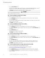
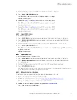
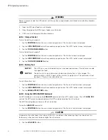
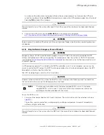
CAUTION
In Bypass mode, the critical load is not protected from commercial power interruptions and abnormalities.
1.
Close the UPS input feeder circuit breaker.
2.
If dual feed, close the UPS bypass feeder circuit breaker.
3.
If IBCs are installed, close the battery breakers.
4.
Observe the UPS control panel display becoming active, indicating logic power.
5.
Verify no alarms are active.
6.
Tap the
CONTROLS
tab on the main menu navigation bar. The System Control screen is displayed.
7.
Tap the
GO TO BYPASS
button.
The critical load is immediately supplied by the bypass source, in Bypass mode.
The
BYPASS
status indicator is illuminated.
Содержание 93PM-L IAC-B
Страница 1: ...p n 164000724 Revision 01 20 200 kW 208V UPS Installation and Operation Manual Eaton 93PM L UPS ...
Страница 10: ...x Eaton 93PM L 20 200kW 208V UPS Installation and Operation Manual 164000724 Rev 01 List of Tables ...
Страница 112: ...102 Eaton 93PM L 20 200kW 208V UPS Installation and Operation Manual 164000724 Rev 01 UPS System Installation ...
Страница 148: ...138 Eaton 93PM L 20 200kW 208V UPS Installation and Operation Manual 164000724 Rev 01 Communication ...
Страница 154: ...144 Eaton 93PM L 20 200kW 208V UPS Installation and Operation Manual 164000724 Rev 01 UPS Maintenance ...
Страница 158: ...148 Eaton 93PM L 20 200kW 208V UPS Installation and Operation Manual 164000724 Rev 01 Product Specifications ...
Страница 161: ...Eaton 93PM L 20 200kW 208V UPS Installation and Operation Manual 164000724 Rev 01 151 Warranty ...
Страница 162: ...16400072401 164000724 01 ...

