computer radio control system
EN
1.
Switch Assignment
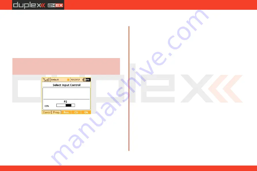
When the menu appears, you can either press the "F1 (Log)“ button
to select/edit a logical switch for your function or you can simply
move the stick, switch or knob that you want to use to control the
function. When you move the chosen control device it will be
recognized and assigned to your function. The control device name
and current status is displayed. Once the control is activated you can
use the function buttons to configure.
Think about what position/direction that you want the
control to work and move the stick, switch or knob into
position before you enter the assignment menu.
Hint:
2.
Proportional Settings
Press the
"F2 (Prop)“
button to make the selected device control
have either proportional or non-proportional control input. This
setting will not be available for all control devices.
For example, you have selected a 3-positon switch for your air
brakes. If you select:
•
Non-proportional – The brake can have only two positions.
•
Proportional – The brake can have up to three positions.
3.
Reversing
Press the
„F3 (Rev)“
button to change the control device activation
direction.
This will not reverse the output direction of your function. It will
simply reverse the direction of the control device (stick,
switch,knob).
4.
Removing the Switch Assignment
Press the
"F4 (Clr)“
button to clear (remove) the selected control
device from your function. You can then select another control
device if you wish or press the
"F5 (Ok)“
button to return to your
function’s menu without assigning any control device.
Once you are happy with your control device seletion and
configuration, press the
"F5 (Ok)“
button or the "3D control“ to
confirm.
5.
Selecting other sources
You can take advantage of several control types that are available in
the dialogue for selecting the control input (press
F1 – F4
buttons to
browse through different types of inputs):
P1 – P8
Physical proportional sticks and proportional
•
controls.
•
Sa – S
f
Physical configurable and replaceable switches.
1)
L1 – L
16
Logical switches.
2)
•
MAX
Logical maximum, can be configured as a switch
•
that is always in an on-state.
GX, GY, GZ
Individual, independent axis of the built-in
•
accelerometers
(not available for DC).
2)
G/L, G/R
Virtual controls switched on at the moment the
•
4.
4.
127
Содержание Jeti DS-12
Страница 1: ...computer radio control system EN DS 12 2 4GHz 900MHz NG Dual Band System EN FW 5 00 CZECH REPUBLIC...
Страница 2: ...computer radio control system EN...
Страница 8: ...computer radio control system EN 8...
Страница 51: ...computer radio control system EN 3 3 51...
Страница 129: ...computer radio control system EN Preview of the individual screens of the dialogue for selecting control input 4 4 129...
Страница 147: ...computer radio control system EN...
Страница 148: ...computer radio control system EN...
Страница 149: ...computer radio control system EN...
Страница 150: ...computer radio control system EN...
Страница 151: ...computer radio control system EN JETI model s r o Lomen 1530 742 58 P bor www jetimodel com...


