


i
Table of Contents
Section 1: System Introduction
1
1.1 Specifications ........................................................................1
1.2 Additional Devices ..............................................................2
1.3 Out of the Box .......................................................................3
Section 2: Getting Started
4
2.1 Installation Steps ..................................................................4
2.2 Terminal Descriptions .........................................................4
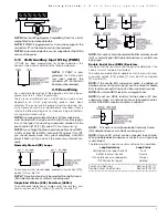
2.3 Wire Routing for Power & Non-Power Limited .............5
2.4 Keybus Operation & Wiring ..............................................5
2.5 Current Ratings – Modules & Accessories .......................6
2.6 Keypad Assignment ............................................................6
2.7 Supervision ...........................................................................6
2.8 Removing Modules ..............................................................6
2.9 Fire Zone Wiring ..................................................................6
2.10 24-Hr Auxiliary Input Wiring (PGM2) ............................7
2.11 Zone Wiring ..........................................................................7
2.12 LINKS Zone Wiring .............................................................8
2.13 Keypad Zones .......................................................................8
Section 3: Keypad Commands
9
3.1 Arming and Disarming .......................................................9
3.2 Auto Bypass – Stay Arming ...............................................9
3.3 Automatic Arming ...............................................................9
3.4 [*] Commands .......................................................................9
3.5 Function Keys .....................................................................12
3.6 Features Available for the LCD5500Z .............................13
Section 4: How to Program
14
4.1 Installer’s Programming ...................................................14
4.2 Programming Decimal Data .............................................14
4.3 Programming HEX Data ...................................................14
4.4 Programming Toggle Option Sections ............................15
4.5 Viewing Programming ......................................................15
Section 5: Program Descriptions
16
5.1 Programming Security Codes ..........................................16
5.2 Zone Programming ........................................................... 16
5.3 Zone Attributes .................................................................. 17
5.4 Assigning Keypad Zones ................................................. 18
5.5 Communicator – Dialing .................................................. 18
5.6 Communicator – Account Numbers .............................. 18
5.7 Communicator – Telephone Numbers ........................... 18
5.8 Communicator – Reporting Codes ................................. 18
5.9 Communicator – Reporting Formats .............................. 19
5.10 Downloading ..................................................................... 21
5.11 PGM Output Options ....................................................... 21
5.12 Telephone Line Monitor (TLM) ...................................... 23
5.13 Bell ....................................................................................... 23
5.14 Test Transmission .............................................................. 24
5.15 Transmission Delay .......................................................... 24
5.16 Fire, Auxiliary and Panic Keys ........................................ 24
5.17 Arming/Disarming Options ........................................... 24
5.18 Entry/Exit Delay Options ................................................ 25
5.19 Swinger Shutdown ............................................................ 25
5.20 Event Buffer ....................................................................... 25
5.21 Keypad Lockout Options ................................................. 25
5.22 Keypad Blanking ............................................................... 26
5.23 Keypad Backlighting ........................................................ 26
5.24 Loop Response ................................................................... 26
5.25 Keypad Tampers ............................................................... 26
5.26 LINKS1000 Cellular Communicator ............................... 26
5.27 Additional System Modules* .......................................... 27
5.28 Resetting Factory Defaults* ............................................. 27
5.29 Installer’s Lockout ............................................................. 27
5.30 Walk Test (Installer) .......................................................... 27
Section 6: Programming Worksheets
28
Appendix A: Reporting Codes
43
Appendix B: Programming LCD Keypads
45
FCC COMPLIANCE STATEMENT
CAUTION: Changes or modifications not expressly approved by Digital Security Controls Ltd.
could void your authority to use this equipment.
This equipment has been tested and found to comply with the limits for a Class B digital device,
pursuant to Part 15 of the FCC Rules. These limits are designed to provide reasonable protection
against harmful interference in a residential installation. This equipment generates, uses and can
radiate radio frequency energy and, if not installed and used in accordance with the instructions,
may cause harmful interference to radio communications. However, there is no guarantee that
interference will not occur in a particular installation. If this equipment does cause harmful inter-
ference to radio or television reception, which can be determined by turning the equipment off
and on, the user is encouraged to try to correct the interference by one or more of the following
measures:
• Re-orient the receiving antenna.
• Increase the separation between the equipment and receiver.
• Connect the equipment into an outlet on a circuit different from that to which the receiver is
connected.
• Consult the dealer or an experienced radio/television technician for help.
The user may find the following booklet prepared by the FCC useful: “How to Identify and
Resolve Radio/Television Interference Problems”. This booklet is available from the U.S. Gov-
ernment Printing Office, Washington D.C. 20402, Stock # 004-000-00345-4.
IMPORTANT INFORMATION
This equipment complies with Part 68 of the FCC Rules. On the side of this equipment is a label
that contains, among other information, the FCC registration number of this equipment.
Notification to Telephone Company The customer shall notify the telephone company of the
particular line to which the connection will be made, and provide the FCC registration number
and the ringer equivalence of the protective circuit.
FCC Registration Number: F53CAN-32028-AL-E
Facility Interface Code: 02LS2
Ringer Equivalence Number: 0.1B
Service Order Code: 9.0F
USOC Jack: RJ-31X
Telephone Connection Requirements
Except for the telephone company provided ringers,
all connections to the telephone network shall be made through standard plugs and telephone
company provided jacks, or equivalent, in such a manner as to allow for easy, immediate discon-
nection of the terminal equipment. Standard jacks shall be so arranged that, if the plug connected
thereto is withdrawn, no interference to the operation of the equipment at the customer’s pre-
mises which remains connected to the telephone network shall occur by reason of such with-
drawal.
Incidence of Harm
Should terminal equipment or protective circuitry cause harm to the tele-
phone network, the telephone company shall, where practicable, notify the customer that tempo-
rary disconnection of service may be required; however, where prior notice is not practicable, the
telephone company may temporarily discontinue service if such action is deemed reasonable in
the circumstances. In the case of such temporary discontinuance, the telephone company shall
promptly notify the customer and will be given the opportunity to correct the situation.
Additional Telephone Company Information
The security control panel must be properly
connected to the telephone line with a USOC RJ-31X telephone jack.
The FCC prohibits customer-provided terminal equipment be connected to party lines or to be
used in conjunction with coin telephone service. Interconnect rules may vary from state to state.
Changes in Telephone Company Equipment or Facilities
The telephone company may
make changes in its communications facilities, equipment, operations or procedures, where such
actions are reasonably required and proper in its business. Should any such changes render the
customer’s terminal equipment incompatible with the telephone company facilities the customer
shall be given adequate notice to the effect modifications to maintain uninterrupted service.
Ringer Equivalence Number (REN)
The REN is useful to determine the quantity of devices
that you may connect to your telephone line and still have all of those devices ring when your
telephone number is called. In most, but not all areas, the sum of the RENs of all devices con-
nected to one line should not exceed five (5.0). To be certain of the number of devices that you
may connect to your line, you may want to contact your local telephone company.
Equipment Maintenance Facility
If you experience trouble with this telephone equipment,
please contact the facility indicated below for information on obtaining service or repairs. The
telephone company may ask that you disconnect this equipment from the network until the prob-
lem has been corrected or until you are sure that the equipment is not malfunctioning.
Digital Security Controls Ltd. 160 Washburn St., Lockport, NY 14094