74
Chapter 11
Internal Fiber Optic Option
Doran’s
GuardianXL
can be supplied with a Fiber Optic Output Option. It can be offered
as part of the Digital I/O Box Option as described in Chapter 8 or it can be installed
inside the
GuardianXL
enclosure. This chapter describes the latter.
The Fiber Optic Output Option is used to provide serial communications. Fiber Optic
can be used for applications with severe electromagnetic noise where standard RS-232
cables will not operate or with long cable runs over 75 feet. The Fiber Optic Option will
provide full duplex bi-directional serial communications.
Fiber Optic Installation
If the indicator was shipped from DORAN with this option installed, refer to Chapter 4,
Communications Parameters for serial output configuration. If you have an existing
GuardianXL
indicator and now require the Fiber Optic option, this section will describe
the installation of the Fiber Optic option.
To install the Fiber Optic option, remove power from the scale indicator and remove the
back panel. The Fiber Optic board will be installed in the lower left quadrant of the
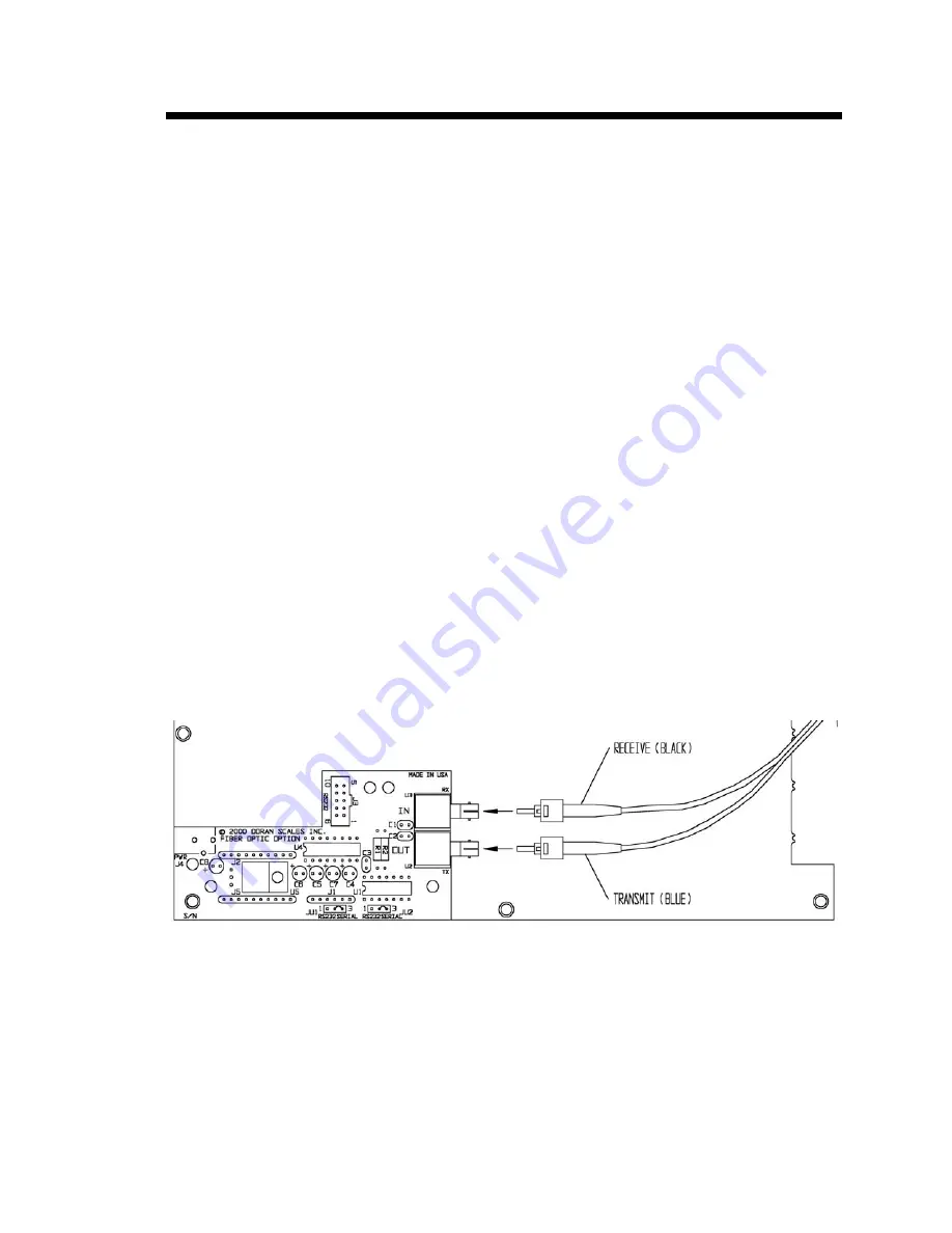
motherboard as you see in figure 11.1 below. The Fiber Optic board comes with three
plastic standoffs installed. These standoffs will mate with the motherboard for a snug fit.
The bottom of the Fiber Optic board has a female header that mates with the J1 six pin
male header on the motherboard. To install the board, ensure the connectors are mating
properly and snap the board into place. The installation of the Fiber Optic board will
block the RS-232 and I/O connectors on the motherboard. To activate the Fiber Optic
Option, move the JU7 and JU6 jumpers on the motherboard to the Fiber Optic positions.
Figure 11.1 Fiber Optic Option
The fiber optic cable is not intended to be installed in a standard water tight as pinching
these cables improperly will cause damage. The Fiber Optic Option will include a
special watertight designed for Fiber Optic use. The watertight requires a 0.900” burr
free hole drilled in the rear cover. This hole is to be drilled 1.5” above the center of the
rightmost watertight hole, when looking at the rear of the panel. Alternatively, a rear
cover can be ordered from DORAN if desired.
Содержание GuardianXL
Страница 2: ...1...
Страница 8: ...7...
Страница 16: ...15...
Страница 18: ...17 Figure 3 1 Motherboard Load Cell Connection and Jumper Location...
Страница 22: ...21...
Страница 38: ...37 REMOVE THIS PAGE AND REPLACE WITH FIG4 7 PDF PRINT B SIZE Figure 4 7 Setup Mode Menu...
Страница 39: ...38...
Страница 55: ...54...
Страница 84: ...83...
Страница 86: ...85 Figure A 1 Indicator Dimensions Dimension A Standard GuardianXL 6 0 GuardianXL with Relay Option 6 5...


