HEC-P6XXX User’s Manual
Document #: 2016002.1.pdf
PAGE 18 of 60
Divelbiss Corporation • 9778 Mt. Gilead Road • Fredericktown, Ohio 43019 • 1-800-245-2327 • www.divelbiss.com
HEC-P6XXX Features
Mounting
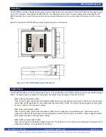
The HEC-P6XXX controller is designed to be panel mounted directly into most environments. The HEC-P6XXX mounts using 4 screws
up to 1/4” in diameter. Even though the HEC-P6XXX can be submerged up to 3 meters in water, ideally, when mounting the HEC-
P6XXX controller, the end with the connectors should be mounted downward as to promote moisture flow away from the connec
-
tions.
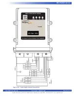
Figure 2.5 illustrates the HEC-P6XXX mounting hole locations and unit dimensions.
Digital Inputs
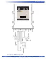
The HEC-P6XXX includes up to 14 on-board digital inputs. They are identified in EZ LADDER Toolkit and this manual as DIN0 through
DIN13. The digital inputs are divided into four groups. Each digital input will operate from 8VDC to 32VDC.
DIN0 - DIN2 (variables DIN0 - DIN2)
These three (3) inputs may be used individually as digital inputs or as high speed counter inputs. These inputs may be config
-
ured as NPN or PNP inputs based on the configuration switches of SW1-1, SW1-2 and SW1-3. When configured as NPN, these
inputs are pulled to the input power voltage.
DIN3 - DIN5 (variables DIN3 - DIN5)
These three (3) inputs may be used individually as digital inputs or together as a quadrature input. These inputs may be
configured as NPN or PNP inputs based on the configuration switches of SW1-4, SW1-5 and SW2-1. When configured as NPN,
these inputs are pulled to the input power voltage.
DIN6 - DIN10 (variables DIN6 - DIN10)
These five (5) inputs are dedicated as digital inputs only. This group has it’s own common pin, allowing this entire group to be
configured as sinking or sourcing based on the wiring.
Figure 2.5 - HEC-P6XXX Mounting & Dimensions
WWW
.DIVELBISS.
C
OM
PWR
I1
I2
ST
S
HARS
H ENVIRONMENT MODULE
SERIAL #:
Embedded
PLC
on a chip™
Fredericktown, Ohio
Patent 7,299,099
HEC-P6XXX
HEC-P6XXX

