


HEC-P6XXX User’s Manual
Document #: 2016002.1.pdf
PAGE 59 of 60
Divelbiss Corporation • 9778 Mt. Gilead Road • Fredericktown, Ohio 43019 • 1-800-245-2327 • www.divelbiss.com
HEC-P6XXX Features
S-RAM SPI Interface Information
Function
Description
Bus / I/O Address
SPI Port
SPI Port used for S-RAM
SPI1
RAM 1 CS
S-RAM, Chip Select
GPIO10
RAM 1 CS
S-RAM, Chip Select
GPIO11
RAM 1 CS
S-RAM, Chip Select
GPIO29
RAM 1 CS
S-RAM, Chip Select
GPIO30
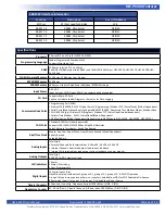
Specifications
Processor
P-Series PLC on a Chip (PLCHIP-P13-51220)
Programming Language
Ladder Diagram with Function Block
Supports Structured Text
RAM
32K bytes total (on PLC on a Chip)
4 Mbit (512K) Battery Backed S-RAM (on 4 1Mbit SPI RAM chips) -HEC-P6010, HEC-P6110, HEC-P6200, HEC-
P6210 only
FLASH Program Memory
512K bytes, 256K bytes User Program
EEPROM Memory
3500 bytes
FRAM Memory
480 bytes. Used for Retentive or additional EEPROM storage.
Input Power
8-32 VDC
Input Current: 12VDC Input: 60mA (no communications enabled)
SD Card
Supports Micro SD Card
Can use to Update Ladder Diagram or Kernel or for Data-Logging
Communications Ports
1 Programming Port (PGM)
1 Ethernet 10/100 MBIT, M12 D-Code (4 pins) (Programming / Modbus TCP / VersaCloud) (Model Dependent)
2 Serial Ports (Model dependent) Configurable RS232/RS485 - Structured Text, Modbus Master, Modbus Slave
1 Wi-Fi 802.11b/g/n Wireless LAN (Program / Modbus TCP / VersaCloud)(model dependent)
1 Cellular Data Modem - 3G(V), (VersaCloud)(Model Dependent)
1 GPS Positioning (Model Dependent) Optional plug-in GPS Module (HEC-P5010, HEC-P5200, HEC-P5210)
CAN Ports
2 Standard CAN Ports (board powered)
Supports SAE J1939, NMEA 2000 and OptiCAN Networks
End of Network Terminator - Switch Configured
Real Time Clock
Month, Day, Year, Day of Week, Hour Minute, Second (Model Dependent)
Battery Backed
Socketed Battery
Analog Inputs
Total Qty 8
4 External Channels, field selectable as 0-20mADC, 0-5VDC or 0-10VDC
3 Internal Channels, dedicated output load current feedback
1 Internal, field selectable as load output current feedback or power monitor
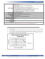
Analog Outputs
Total Qty 2
0-10VDC, 1mADC maximum load
LED Indicators
1 Power
1 Status / Watchdog
2 User Programmable
Digital Inputs
14 Digital Inputs Total
Optically isolated, Divided into 1 group of 6, 1 group of 5, 1 group of 3. 8-32VDC Operation.
Group of 6 Inputs may operate as timers or counters, Selectable as NPN or PNP. Selectable De-bounce.
8 Remaining Inputs, 1 group of 5, 1 group of 3. Selectable as Sink or Source.
Timers /Counters
3 Channels, (Count Up, Frequency, Period) 100KHz Max. (DIN0 - DIN2).
Quadrature Counter
X1, X4, Up/Down, 3 Inputs Channels, A, B and Index. 100KHz Max. (DIN3 - DIN5)


