


HEC-P6XXX User’s Manual
Document #: 2016002.1.pdf
PAGE 24 of 60
Divelbiss Corporation • 9778 Mt. Gilead Road • Fredericktown, Ohio 43019 • 1-800-245-2327 • www.divelbiss.com
HEC-P6XXX Features
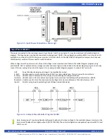
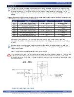
Quadrature Input
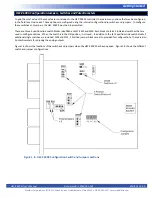
As was noted in the Digital Inputs Section, three of the digital inputs (DIN3, DIN4, DIN5) may be utilized together as a quadrature
input that can accept signals from a quadrature encoder. When configured as quadrature inputs (DIN3, DIN4 and DIN5 as CHA, CHB
and INDEX respectively), can accept frequencies up to 100KHz. Each input is optically isolated to promote noise immunity.
Each of the DIN2, DIN3 and DIN4 inputs have software enabled de-bounce circuitry. This circuitry typically should be
enabled when these inputs are being used as digital inputs. When configured as quadrature inputs, the de-bounce should
typically be disabled.
The de-bounce circuits for each input (DIN3 - DIN5) are enabled and disabled by adding the variables (coils) named DIN3_DEB,
DIN4_DEB and DIN5_DEB respectively. When the variable (coil) is true, the de-bounce circuit is enabled and when the coil is false,
the de-bounce circuit is disabled. The variables DIN3_DEB, DIN4_DEB and DIN5_DEB are automatically created by EZ LADDER when
the HEC-P6000 target is selected.
Deleting the de-bounce variables from the program will cause the de-bounce circuit to be enabled resulting in inputs not
operating properly.
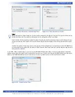
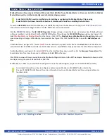
Prior to using the quadrature inputs in the ladder diagram, the Quadrature Encoder Interface functionality must be installed and
configured in the ladder diagram’s Project Settings.
The first step to installing the quadrature encoder interface is to install the PLCHIP_Pxx_qei (Internal Quadrature Encoder Interface)
feature. Using menu, click
PROJECT
then
SETTINGS
to open the Project Settings window. With the target HEC-P6000 selected still,
click the
PROPERTIES
button. The HEC-P6000 Properties Window will open. Verify the proper actual part number is selected in
the Drop-down Part Number select box. Under the Devices, Internal section, if the quadrature encoder interface were installed, it
would be listed.
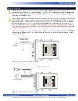
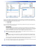
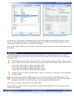
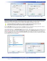
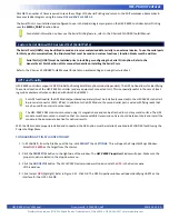
To install the Quadrature Encoder Interface, click the
ADD DEVICE
button. From the available devices, select
PLCHIP_Pxx_qei
and
click
OK
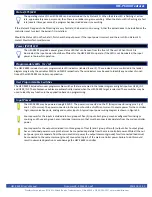
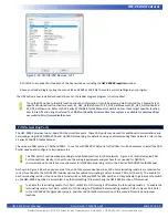
. Refer to Figure 2.13. The PLCHIP_Pxx_qei Properties window will now open. See Figure 2.14.
The PLCHIP_Pxx_qei Properties window is used to configure the quadrature encoder interface for DIN3, DIN4 and DIN5. Some of
the common and simple settings such as Quadrature Mode and Flags are set in this window. Other additional settings are available
for configuration. Refer to the P-Series EZ LADDER Toolkit User’s Manual for details on the Quadrature Encoder Interface configura
-
tions.
Select the
Quadrature Mode
and any other required settings. Click
OK
. the number of times necessary to close and save all the con
-
figurations. You should return to the EZ LADDER Toolkit’s Edit workspace by clicking
OK
. the number of times required. Remember
to Save your ladder diagram using the menu
FILE
and
SAVE
or
SAVE AS.
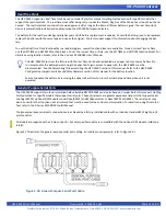
To use DIN0 - DIN3 in a ladder diagram as a quadrature encoder interface, you must use the CNTR_PXX_QEI, CNTR_PXX_QEI_CMP
or CNTR_PXX_QEI_VEL function blocks. Each block has a specific function and relationship to the quadrature encoder interface
inputs. Refer to the P-Series EZ LADDER Toolkit User’s Manual for details on each of these function blocks.
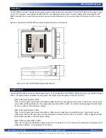
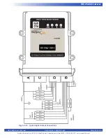
Each high quadrature encoder interface input can be field selected as either PNP (current sinking) or NPN (to accept signals from
open-collector output devices). The type of device is selected by internal dip-switch settings on the HEC-P6XXX. To gain access to
these dip-switches, the HEC-P6XXX must be dis-assembled. See the Assembling / Dis-assembling the HEC-P6XXX section of this
manual.


