HEC-P6XXX User’s Manual
Document #: 2016002.1.pdf
PAGE 30 of 60
Divelbiss Corporation • 9778 Mt. Gilead Road • Fredericktown, Ohio 43019 • 1-800-245-2327 • www.divelbiss.com
HEC-P6XXX Features
Analog Outputs
The HEC-P6XXX provides 2 on-board, 12-bit resolution analog outputs rated 0-10VDC. A calibration potentiometer is
provided for minor field calibration (if required) for each channel. To gain access to these potentiometers, the HEC-P6XXX
must be dis-assembled. See the Assembling / Dis-assembling the HEC-P6XXX section of this manual. Refer to the
HEC-P6XXX Configuration Jumpers, Switches and Potentiometers
section of this manual for poteniometer locations.
Each analog output is represented in the EZ LADDER Toolkit ladder diagram using variables labeled AOT0 and AOT1
respectively. The variables were created automatically when the HEC-P6000 target was selected in the Project Settings
Window.
Each variable (AOT0 - AOT1) will control the actual output voltage (per channel). Changing the variable (integer number
of 0-4095), where 0 is approximately 0VDC and 4095 is 10VDC will result in the analog output voltage changing
accordingly.
The analog outputs are factory calbirated, but if the analog output is less than or greater than 10.00VDC if the variable is
set to 4095, then minor field adjustments may be required. To calibrate a channel, measure the output voltage with a
digital voltmeter (DVM), set the channel output variable to 4095 and adjust the channel’s potentiometer until the output
voltage reads 10.00VDC on the DVM.
Channel 0: AOT0, uses potentiometer R90
Channel 1: AOT1, uses potentiometer R93
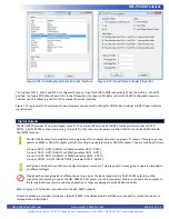
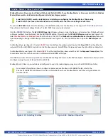
The analog outputs have a limited current sourcing potential. They are not designed to source loads over 1mADC. Figure 2.19 il
-
lustrates the typical internal output circuit. The analog output circuits should be connected to other driver circuits to control heavier
loads.
Figure 2.19 - Typical Analog Output Circuit

