background image

1

InfoServer 100 System

The InfoServer 100 is a general-purpose disk storage server that quickly

and efficiently transfers data between disks connected to the server and

remote network

client systems

. It provides users with a low-cost data

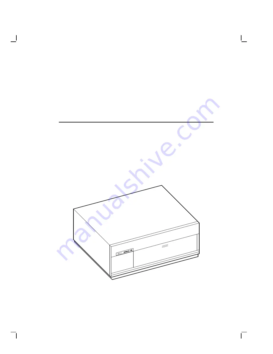
sharing capability that is flexible and easy to manage. Figure 1–1 shows

the system enclosure for InfoServer 100.
The InfoServer 100 can support many diverse applications. For example,

VMS client systems can share software distribution and documentation

on compact discs connected to the server. Some VAX systems can use the

server to load their

bootstrap

program, then perform a VMS operating

system installation from a compact disc in the server.

L J - 0 0 0 6 2 - T I 0

Figure 1–1

InfoServer 100 System Enclosure

1–1

Содержание InfoServer 100

Страница 1: ...InfoServer 100 Installation and Owner s Guide Order Number EK DIS1K IN 001 This manual describes how to install test operate and maintain the InfoServer 100 system Digital Equipment Corporation...

Страница 2: ...ghts Reserved Printed in U S A FCC NOTICE The equipment described in this manual generates uses and may emit radio frequency energy The equipment has been type tested and found to comply with the limi...

Страница 3: ...ers 2 6 Attach the Ethernet Terminators 2 7 Connect the System Unit Power Cord 2 9 Connect a Console Terminal 2 10 Connect External Expansion Boxes 2 11 Starting Your System 2 12 Loading A Compact Dis...

Страница 4: ...Resetting the SCSI ID on the Second RRD40 Expansion Box 4 11 5 Connecting to a Network A Brief Introduction to Networks 5 1 Connecting to a ThinWire Ethernet Network 5 3 Check the Network Select Butto...

Страница 5: ...Running Test Utilities 6 13 RRD40 Test Disc Utility 6 13 Restarting the System After Running Tests 6 13 Command Summary 6 14 Service Information 6 16 A SCSI IDs SCSI ID Default Settings A 1 Setting th...

Страница 6: ...s 4 10 D 1 Compact Disc Caddy D 1 D 2 Inserting or Removing a Disc from the Housing D 2 Tables 1 Conventions viii 4 1 SCSI Devices Self Test Status Codes 4 11 6 1 Troubleshooting Basic System Problems...

Страница 7: ...e InfoServer 100 system The guide requires little or no previous experience with computers Structure of This Guide This manual contains six chapters four appendixes and a glossary of technical terms C...

Страница 8: ...guide For More Information See Appendix C for a list of related documents to help you become acquainted with your new system Conventions The following conventions are used in this guide Table 1 Table...

Страница 9: ...and easy to manage Figure 1 1 shows the system enclosure for InfoServer 100 The InfoServer 100 can support many diverse applications For example VMS client systems can share software distribution and...

Страница 10: ...o standard Ethernet or ThinWire Ethernet work groups and networks but not to both types at the same time RRD40 compact disc drive One or two compact disc drives are mounted behind the server s front p...

Страница 11: ...chronous port with MMJ connector for VT series terminals is provided as standard You can use this port to connect a terminal to the server to establish a local server management session See the InfoSe...

Страница 12: ......

Страница 13: ...its best Carefully read all installation instructions before you turn on the power Keep the air well circulated to prevent excess heat and dust from accumulating Keep your equipment away from heaters...

Страница 14: ...is shipped in two boxes one for hardware and one for software The larger box contains the InfoServer 100 hardware with accessories and documentation The smaller box contains the software compact disc...

Страница 15: ...CESSORIES Two Terminators and One T Connector ThinWire Ethernet Connector Covers SCSI Terminator Loopback Connector Standard Ethernet Server System Unit Drive Label Pockets Operator s Card L J 0 0 0 5...

Страница 16: ...ons identify each port and connector you will use when installing your system On Off Switch System AC Power SCSI Port Standard Ethernet Connector Standard Ethernet Light Network Select Button ThinWire...

Страница 17: ...Install the SCSI Terminator If you do not intend to connect additional drives to your system install the SCSI terminator on the SCSI port at the rear of the system unit as shown MLO 003288 SCSI Termi...

Страница 18: ...nector Covers You system comes with three connector covers to protect the unused connectors on the rear panel of the system unit If you do not use the external SCSI interface install cover 1 over the...

Страница 19: ...the ThinWire Ethernet circuit Later when you decide to connect to a network you exchange ThinWire cable sections for one or both terminators depending on your network setup The loopback connector comp...

Страница 20: ...the T connector clockwise until it locks into place T Connector MLO 002752 M A 0 3 5 7 9 0 D G 4 Connect the loopback connector to the standard Ethernet port on the back of the system unit If needed r...

Страница 21: ...of 100 Vac to 120 Vac and 200 Vac to 240 Vac at 50 or 60 Hertz Within these limits the power supply is self sensing so the system unit does not need a voltage selection switch Connect the supplied pow...

Страница 22: ...ar of the VT300 series terminal the port must be set for DEC 423 operation See your terminal documentation for details To connect a terminal to the server NOTE Make sure the l O power switch on the te...

Страница 23: ...lable or if client systems have trouble accessing server services then a locally connected terminal is needed to manage the server or diagnose server problems See the InfoServer 100 System Operations...

Страница 24: ...f you see a display similar to the following your system has passed all power up tests and the terminal s keyboard language has been set KA41 A V1 3 F_ E D C B A 9 8 7 6 5 4 3 2 1 E 0040 0000 0005 D 0...

Страница 25: ...et Address Label Drive Labels Compact Disc Drive Compact Disc Drive Use the following procedure to load the software compact disc when starting the system Load the disc in the drive on the right The d...

Страница 26: ...ed improperly in the caddy Stop loading the disc and refer to Appendix D 3 Slide the caddy in the drive as far as it will go 2 then remove it 3 When you remove the caddy notice that the disc and its h...

Страница 27: ...Installing Your System 2 15 L J 0 0 0 5 6 T I 0 3 2 1...

Страница 28: ...nnecting to a Network After you verify that the InfoServer 100 passes its power up self test sequence you must connect it to the network to make it available to client systems To connect to a network...

Страница 29: ...drive at the factory After the power up display the server automatically tries to bootstrap from the software image on the software disc you placed in the right compact disc drive The compact disc dri...

Страница 30: ...0 s software compact disc This procedure should take less than 60 seconds 1 Make sure the system unit s l O power switch is off O 2 Connect the console terminal 3 Turn the system unit s l O switch on...

Страница 31: ...he following combinations Mounting Panel Position Upper Left Center Right RZ23 Lower Left Right RRD40 RRD40 RZ23 Hard Disk The RZ23 is a nonremovable hard disk that can store 104 Mbytes of information...

Страница 32: ...ion and database storage You can increase the number of compact disc drives on your server by using RRD40 expansion boxes See Chapter 4 to learn about these add on devices Console Terminal The InfoSer...

Страница 33: ...ve can support up to seven expansion boxes Digital qualifies the external expansion boxes recommended for use with the InfoServer 100 to ensure that they meet system requirements The chapter provides...

Страница 34: ...r expansion box to an unused bottom SCSI connector on the back of an expansion box You should plug all expansion boxes into the same grounded power strip or electrical outlet CAUTION Some expansion bo...

Страница 35: ...nected to the SCSI port 1 To remove the SCSI cover place your fingers under the locking tab and lift the cover to release MLO 002766 SCSI Cover Lift Locking Tab to Release M A 0 3 7 7 9 0 D G 2 Remove...

Страница 36: ...es long If a longer cable is used the system expansion capability is reduced One power cord Before you set up your expansion box make sure you have all the parts shown in Figure 4 1 Check the contents...

Страница 37: ...left to right Refer to the information provided with the expansion box to determine how the switches are set 4 Connect the 50 pin to 50 pin expansion box cable as follows Connect one end of the cable...

Страница 38: ...xpanding Your System Figure 4 2 shows how to connect one RRD40 expansion box to the system Connector Cable Terminator Power Cord MLO 002763 M A 0 3 8 2 9 0 D G Figure 4 2 Connecting One RRD40 Expansio...

Страница 39: ...n power off the system unit 2 Remove the 50 pin terminator on the first expansion box Store the terminator for future use 3 Connect one end of the 50 pin to 50 pin connector cable to the upper connect...

Страница 40: ...4 8 Expanding Your System To Host SCSI Port Terminator L J 0 0 0 6 1 T I 0 Figure 4 3 Connecting Two RRD40 Expansion Boxes...

Страница 41: ...pact disc MLO 000971 Power Light Activity Light L J 0 0 0 8 6 T I 0 Opening for Compact Disc Power light Turns on when you turn on your system unit Activity light Turns on when you load a compact disc...

Страница 42: ...shipped with the SCSI switches set to number 0 as shown in Figure 4 4 1 1 0 2 2 0 Voltage Selector Bail Lock Power Cord M L O 0 0 2 3 2 5 L J 0 0 0 5 8 T I 0 SCSI ID 0 D o w n D o w n D o w n D o w n...

Страница 43: ...appears on the screen FFFFFF05 indicates an open SCSI ID Look for a display similar to the following SCSI B 1C1C 0001 V1 3 FFFFFF05 05000001 05000001 05000001 05000001 05000001 FFFFFF03 FFFFFF05 1 2...

Страница 44: ......

Страница 45: ...etworks Networks allow people to work together on projects and share information They can communicate and exchange information share common databases share files and disk storage share printers or use...

Страница 46: ...n All Digital Ethernet products can connect to ThinWire cable ThinWire cable can be used in any size system and is fully compatible with standard Ethernet communication ThinWire is ideal for small sta...

Страница 47: ...e system unit When you first receive the system the button is usually set to the in position In ThinWire Ethernet Out Standard Ethernet To use ThinWire Ethernet on your system make sure the button is...

Страница 48: ...B A 9 8 7 6 5 4 3 2_ 1 2 The console prompt also appears If the console prompt does not appear press the halt button on the back of the system unit Halt Button MLO 002754 M A 0 3 6 2 9 0 D G 3 Enter t...

Страница 49: ...or for the system unit 3 If your system is the first or last system in a single ThinWire segment leave the terminator attached to one side of the T connector A segment is a length of cable made up of...

Страница 50: ...5 Make sure the T connector is attached correctly to the back of the system unit Push the T connector onto the system unit BNC connector then turn it clockwise until it locks in place T Connector MLO...

Страница 51: ...single network connection for your system DECconnect cabling components support network configurations ranging from simple standalone ThinWire networks to multimedia local area networks LANs that conn...

Страница 52: ...G Troubleshooting the ThinWire Segment If you find problems during the ThinWire Ethernet installation use the following checklist to make sure all connections are correct 1 Check that all connections...

Страница 53: ...connection 5 Check that a ThinWire segment is not looped from one port on the DEMPR to another port on the DEMPR 6 Check that the system unit s T connector has not been disconnected from an operating...

Страница 54: ...pt network operation After you have checked all ThinWire Ethernet connections retest the Ethernet Enter the following command at the console prompt TEST 1 Return or T 1 Return If a connection is estab...

Страница 55: ...ttach the 15 pin standard Ethernet loopback connector to your system unit 1 Turn on your system A power up display similar to the following appears F_ E D C B A 9 8 7 6 5 4 3 2_ 1 The light at the end...

Страница 56: ...ansceiver or DELNI unit which is attached to the standard Ethernet cable To connect a transceiver cable to your system 1 Set the l O on off switch on the rear of the system unit to off O 2 Connect the...

Страница 57: ...active Ethernet segment you can test the system without the loopback connector 2 Turn your system off then turn it on again The system verifies the Ethernet connection during the power up sequence 3 A...

Страница 58: ......

Страница 59: ...r Running test utilities for expansion boxes Restarting the system after tests Command summary Service information If a Problem Occurs If a problem occurs first make sure that all power and SCSI cable...

Страница 60: ...he following steps 1 Note the symptoms of the problem 2 Check the symptom column in Table 6 1 for a match 3 Check the conditions for that symptom in the Possible Cause column If more than one possible...

Страница 61: ...power outlet may not be working Try a lamp that you know works in the outlet The terminal fuse may have blown Check the brightness and contrast controls Replace blown terminal fuse Terminal settings...

Страница 62: ...rver 100 system software is not installed See Starting Your System in Chapter 2 The system unit s power light is off The system unit s l O power switch is not turned on Check the setting of the l O po...

Страница 63: ...0005 indicates a low battery The system battery s charge is low or completely discharged Run the system for about 17 hours to fully recharge the battery If you see single question marks in the power...

Страница 64: ...back connector is not installed on the standard Ethernet port The terminator is not installed on the ThinWire Ethernet port The network select switch is set to the wrong position A cable is faulty Tab...

Страница 65: ...he status of the device tested To test a device in your system 1 Use Table 6 2 to find the number or letter that represents the device you want to test NOTE The halt button halts the system 2 Put the...

Страница 66: ...r codes Configuration Display This procedure displays the system configuration Ethernet ID ROM revision levels and status information for your InfoServer 100 Error information in this display is valua...

Страница 67: ...00000000 2 3 4 5 6 7 MEM 0004 0001 8 00400000 MM 0000 0001 FP 0000 0001 IT 0000 0001 SCSI A 7711 0001 V0 1 004C437 0004C437 00000000 00000000 SCSI B 1C1C 0001 V1 0 FFFFFF03 FFFFFF05 05000001 FFFFFF03...

Страница 68: ...ID ROM Displaying Device Information To determine what devices are installed in your system and their SCSI bus ID assignments enter the SHOW DEVICE command at the console prompt SHOW DEVICE Return Yo...

Страница 69: ...ware media Insert the RRD40 test disc into the RRD40 compact disc drive before running the system exerciser The test disc is supplied with the drive To test your system 1 Enter the TEST 50 command at...

Страница 70: ...us indicators if any 4 Mnemonic for the device 5 Error or status information for each device 6 Number of times device was tested 7 Progress count indicates progress within some tests 8 The time days h...

Страница 71: ...nce Restarting the System After Running Tests While running any of the tests or procedures in this chapter your system is in console mode If the InfoServer system software is already loaded on the int...

Страница 72: ...t SET HALT Default halt action SET SCSIA Sets the SCSI device ID number bus A SET SCSIB Sets the SCSI device ID number bus B SET BOOT Sets the bootstrap device SET BFLG Sets the bootstrap address Tabl...

Страница 73: ...ry action flags TEST 76 SCSI diskette formatter Table 6 6 SHOW Command Summary Command Information Displayed SHOW DEVICE Devices available and SCSI ID SHOW ESTAT Results of last system exerciser test...

Страница 74: ...service representative may need this number when you call 2 Make notes based on the troubleshooting table at the beginning of this chapter This information may tell your service representative the sta...

Страница 75: ...gs You are responsible for the SCSI ID settings on your equipment Digital sets each SCSI device to a default setting before the equipment leaves the factory You may never need to change a default sett...

Страница 76: ...internal switches or jumpers If you need to change their default settings the setting must be reset by your Digital service representative Setting the SCSI ID Enter the TEST 50 command at the console...

Страница 77: ...ou use only Digital supplied cable assemblies intended for interconnecting SCSI devices This ensures that the impedance characteristics signal propagation velocity inductance capacitance cross talk gr...

Страница 78: ...Positions Switches 1 2 3 and 4 SCSI B Bus 1 2 3 4 0 Down Down Down Not used 1 Down Down Up Not used 2 Down Up Down Not used 3 Down Up Up Not used 4 Up Down Down Not used 5 Up Down Up Not used 6 Up Up...

Страница 79: ...ive 1 or 2 600 Mbyte RRD40 internal drives depends on configuration Optional storage RRD40 expansion boxes Terminals Supports the VT series Interfaces 1 SCSI port 1 ThinWire Ethernet port 1 standard E...

Страница 80: ...o 40 C 50 to 104 F Temperature change rate 11 C hour 20 F hour maximum Relative humidity 10 to 90 noncondensing Maximum wet bulb temperature 28 C 82 F Minimum dew point 2 C 36 F Altitude 2400 m at 36...

Страница 81: ...ed Documents Titles Order Number InfoServer 100 Documentation InfoServer 100 System Operations Guide EK DIS1K UG InfoServer 100 Installation and Owners Guide EK DIS1K IN InfoServer 100 Operators Guide...

Страница 82: ...neral Description EK DECSY GD DECconnect System Requirements Evaluation Workbook EK DECSY EG DECconnect System Installation and Verification Guide EK DECSY VG DECconnect System Standalone ThinWire Net...

Страница 83: ...the compact discs Compact Discs The RRD40 compact disc drive uses compact discs with a memory capacity of 600 Mbytes The discs come in a protective caddy for insertion into the compact disc drive The...

Страница 84: ...fingernail or a sharp pointed instrument 3 When both tabs have been unlocked pull the disc housing out to about the midpoint of the disc 4 Hold the disc housing on each side Exert inward pressure on...

Страница 85: ...rooved to accept the disc Exert inward pressure to hold the disc in the housing 4 Slide the housing into the transparent sleeve until the housing clicks into place 5 Turn the assembled caddy over so t...

Страница 86: ......

Страница 87: ...e A set of 7 or 8 bit binary numbers representing the alphabet punctuation numerals and other special symbols used in text representation and communications protocol barrel connector A female connecto...

Страница 88: ...m travel byte A group of eight binary digits bits A byte is one quarter of a VAX system longword caddy A compact disc holder used to inserting a compact disc into a compact disc drive central processi...

Страница 89: ...ystem component usually a printed circuit board that regulates the operation of one or more peripheral devices CPU Abbreviation for central processing unit See central processing unit daisy chain A gr...

Страница 90: ...nd is capable of receiving storing or transmitting data See input output I O device and controller device icon An icon on the rear of the system unit that represents the device that can be plugged int...

Страница 91: ...ated by the system as a single unit format To prepare a diskette to accept data formatted data Data that is structured in a particular pattern to be understood by the system software ground A voltage...

Страница 92: ...the system enclosure link A communications path between two nodes A physical link is the electrical connection between two nodes A logical link implies that two nodes are able to communicate whether o...

Страница 93: ...Repeaters perform the basic actions of restoring signal amplitude waveform and timing amplitude to normal data and collision signals multisegment LAN A LAN composed of more than one cable segment net...

Страница 94: ...diskette drives video terminals and printers port Another term for a connector on a device such as a computer or server used to make a connection to another device such as a terminal printer or commun...

Страница 95: ...ThinWire Ethernet cable terminated at each end with a connector segment A length of cable made up of one or more cable sections connected with barrel connectors or T connectors server Hardware or soft...

Страница 96: ...sections The connector also has a connector that is attached directly to a system terminal An input output device that lets you communicate with the system Terminals are divided into two categories v...

Страница 97: ...A switch on the front of the TZ30 tape drive that rewinds and unloads the tape unshielded twisted pair cable Multiple conductor cable whose component cables are paired twisted and enclosed in a singl...

Страница 98: ......

Страница 99: ...ons ports 1 3 baud rate 1 3 Compact disc loading 2 13 RRD40 3 2 testing 6 13 unloading 2 16 use and storage of D 1 Compact disc caddy 2 13 Compact disc drive 1 2 See also RRD40 compact disc drive turn...

Страница 100: ...Disk drives RZ23 3 1 turning off 2 16 turning on 2 12 Drive mounting panel lower 3 1 upper 3 1 E Environmental requirements 2 1 Error message RRD40 6 11 Error messages configuration 6 8 double questi...

Страница 101: ...er See Bootstrapping 2 17 Inserting compact disc 2 13 D 3 Installation 2 1 to 2 18 Installation Cont connector covers 2 6 console terminal 2 10 Ethernet T connector and terminators 2 7 location 2 1 lo...

Страница 102: ...2 Operating system software restarting 6 13 Outlets grounded 2 2 P Password lost 2 18 Peripheral devices 4 1 See also the specific device 4 1 supported number of 4 1 Ports 2 4 baud rate 1 3 Power cor...

Страница 103: ...em exerciser 6 12 device A 1 RRD40 switches A 3 setting switches A 3 SCSI Cont switch locations A 2 terminator 2 5 terminators 4 2 4 5 A 3 removing 4 3 SCSI IDs creating custom configurations A 1 defa...

Страница 104: ...11 display example 6 11 restarting after running 6 13 testing media 6 11 when to use 6 11 System SCSI IDs A 2 System specifications operating conditions B 2 System unit System unit Cont attaching Eth...

Страница 105: ...ing 5 8 verifying 5 4 ThinWire Ethernet segment defined 5 5 Transceiver cable 5 12 Transparent sleeve compact disc 2 16 Troubleshooting 6 1 to 6 16 configuration display 6 8 expansion box 6 4 lights L...

Страница 106: ......

Отзывы: