Digga Magnum II Series Скачать руководство пользователя страница 38

38

M

N

L

8.

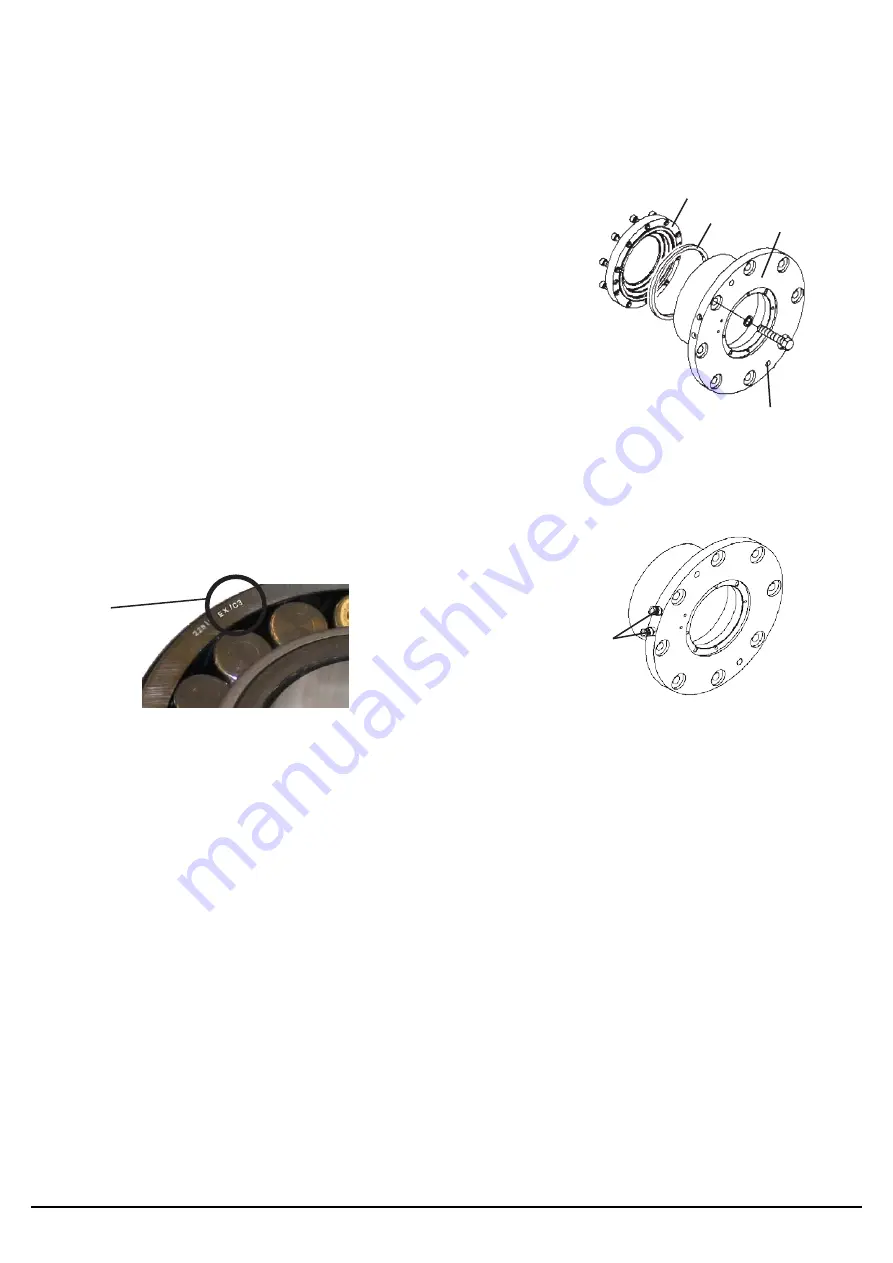
Remove the eight .50” cap screws from the bearing housing

(L) and install two of them into the push off holes to aid in the

removal of the bearing housing. Remove the bearing housing.

NOTE: 

When removing the cap screws on the left lower bearing housing 

the grease fitting protection guard will also be removed.

9.

Remove the ten socket head cap screws from the inner seal cap

(M) and remove the inner seal cap and spacer ring (N - right

side bearing only).

NOTE: 

Two of the cap screws may need to be installed into the push 

off holes in the inner seal cap for removal.

10.

Slide or press the bearing out the back of the housing (L).

11.

Inspect the inside of the bearing housing, the withdrawal sleeve

and rotor shaft for defects, such as burrs, worn surfaces or any

surface imperfections. Inspect the rotor shaft seals for damage.

NOTE: 

It is recommended to replace rotor shaft seals when replacing

bearings.

PUSH OFF HOLE

C3

LOWER RIGHT HOUSING 

IDENTIFICATION

LOWER RIGHT BEARING IDENTIFICATION

NOTICE:

Although the left and right bearings look alike they are different. Be sure to identify and

install the correct bearing during replacement. The right side bearing #600-158 will have a “C3” on

the bearing rim while the left bearing #115439 will not. All other identification marks, letters and

numbers are related to manufacturer and do not have any significance in distinguishing between the 

two bearings. Take extra care to install the correct bearing into the correct housing. The right bearing

housing will have the grease and relief ports on the outside flange diameter of the housing while the 

left side bearing housing will have the grease and relief ports on the outside flange face of the

bearing housing.

12.

Clean all lower bearing components and rotor shaft, removing all grease and contaminants.

Apply a light coat of machine oil to the inside of the bearing housing and install the new bearing

with the smaller side of the taper in the bearing inner race to the inside of the housing. Check

diagram for correct bearing orientation.

a. Position the bearing as straight as possible with the bearing housing.

b. Position a tube over the bearing, contacting the outer race of the bearing only, and

lightly tap until the bearing is aligned with the housing.

c. Once alignment has been achieved the left side bearing will easily slide into place

while the right side bearing will need a press. Ensure right bearing is fully seated into

the housing.

NOTE: 

Apply force to the outer race of the bearing only to prevent damage.

MAINTENANCE & SERVICE

QUALIFIED TECHNICIAN MAINTENANCE

PM-000102-A  OCTOBER 2017

37

Содержание Magnum II Series

Страница 1: ...OPERATOR S AND PARTS MANUAL MAGNUM MULCHER SERIES II FOR SKID STEER AND EXCAVATOR SERIAL NUMBER MODEL NUMBER PM 000102 A...

Страница 2: ......

Страница 3: ...BY STANDERS AND LIVESTOCK BEFORE OPERATING THE MULCHER IS CAPABLE OF PRODUCING LARGE AMOUNTS OF FLYING DEBRIS IN ALL DIRECTIONS WARNING BEFORE LEAVING THE OPERATOR S SEAT LOWER THE LIFT ARMS AGAINST...

Страница 4: ...Tie Down Points 26 Transporting 26 MAINTENANCE AND SERVICE Maintenance Schedule 27 Lubrication Specifications 28 Replacing Teeth 29 Drive Belt Tensioning and or Removal 29 Sprocket Removal and Install...

Страница 5: ...rimary responsibility for safety with this equipment falls to the operator Make sure the equipment is operated only by trained individuals that have read and understand this manual If there is any por...

Страница 6: ...d the prime mover thoroughly before beginning installation operation or maintenance FOLLOW ALL SAFETY INSTRUCTIONS IN THIS MANUAL AND THE PRIME MOVER S MANUAL S READ AND UNDERSTAND ALL SAFETY STATEMEN...

Страница 7: ...or death Hydraulic leaks under pressure may not be visible Before connecting or disconnecting hydraulic hoses read your prime mover s operator s manual for detailed instructions on connecting and disc...

Страница 8: ...re they are in good condition for the task required Wear the protective equipment specified by the tool manufacturer SAFELY OPERATE EQUIPMENT Do not operate equipment until you are completely trained...

Страница 9: ...lastic etc Follow all federal state and local regulations for recycling and disposal of the fluid andcomponents OPERATING THE MULCHER Block off work area from bystanders livestock etc Flying debris ca...

Страница 10: ...spilled fuel Secure cap tightly when done MAINTAINING THE MULCHER Before performing maintenance disengage auxiliary hydraulics lower the attachment to the ground turn off the engine remove the key an...

Страница 11: ...591 40719 40591 MODEL NUMBER 41059 40591 4167 40151 41020 40161 41200 40591 4167 4167 40151 40591 40719 41200 40719 40719 40591 41087 41059 40949 41204 40307 SERIAL TAG LOCATION 4132 LOGO 41020 IMPORT...

Страница 12: ...H PRESSURE FLUID PART 40151 DANGER ROTATING DRUM PART 40591 DANGER STAND CLEAR PART 4105 WARNING GUARDS PART 40949 CLEAN DEBRIS 40 HOURS PART 41087 DANGER GUARD MISSING PART 40307 NOTICE MOTOR FAILURE...

Страница 13: ...41192 MANUAL STORAGE INSIDE PART 41059 MULCHER LOGO PART 41020 GREASE EVERY 200 HOURS PART 41166 CHECK OIL LEVEL PART 4132 NOTE Contact your local dealer for model number and logo decals DIGGA LOGO S...

Страница 14: ...teer loader mulchers 66 CC on the combination and excavator mulchers and 76 CC on the forestry mulchers NOTICE Insufficient RPM below 1800 will greatly reduce the productivity of your unit while over...

Страница 15: ...83 58 30 22 61 170 33 66 30 18 03 62 80 20 07 59 60 21 84 LPM DISPLACEMENT CC SCREW M12X100 DIMENSION X mm DISPLACEMENT CC SCREW M12X100 DIMENSION X mm DISPLACEMENT CC SCREW M12X100 DIMENSION X mm 13...

Страница 16: ...0 99 61 40 32 51 58 30 33 78 170 33 66 30 30 23 62 80 31 75 59 60 33 27 174 11 67 70 29 46 64 20 31 24 60 90 32 77 177 90 69 20 28 96 65 60 30 48 62 30 32 00 181 68 70 70 28 19 66 90 29 97 63 60 31 50...

Страница 17: ...r mounting to excavator mounting A special 60 mulcher is designed for a universal skid steer hitch forestry vehicle When installing a hydraulic 3 line mulcher onto your prime mover a control box assem...

Страница 18: ...E MULCHER IS SECURELY LATCHED TO THE ATTACHMENT MECHANISM OF YOUR UNIT FAILURE TO DO SO COULD RESULT IN SEPARATION OF THE ATTACHMENT FROM THEUNIT CLEAR THE AREA OF ALL BYSTANDERS DURING INSTALLATION I...

Страница 19: ...eroute hoses before operating Route hoses in such a fashion to prevent pinching or chafing WARNING TO AVOID SERIOUS PERSONAL INJURY MAKE SURE THE MULCHER IS SECURELY LATCHED TO THE ATTACHMENT MECHANIS...

Страница 20: ...ox 15754 or pigtail adaptor going to in cab electrical outlet 4 Remove the push over bar 5 Adjust motor displacement for correct rotor RPM See Set Upinstructions TO CHANGE FROM EXCAVATOR MOUNTING TO S...

Страница 21: ...ng to prevent over pressurization of the motor case causing severe hydraulic system damage which is not covered by warranty OPERATION INTENDED USE This unit was designed to mulch brush and small trees...

Страница 22: ...for an extended amount of time Running the mulcher at maximum pressure levels can shorten the life of the hydraulic components Operating the unit slightly below maximum pressure will create less heat...

Страница 23: ...to follow this shut down and restart procedure will cause severe damage to the hydraulic system of the attachment and void all warranties Care must be taken when shutting the high flow switch to the...

Страница 24: ...Excavator When clearing brush start at the top and using a sweeping action swing the unit back and forth through the brush while lowering at a pace that will not decrease the rotor rpm Once you are c...

Страница 25: ...n overhung load adapter See Maintenance instructions NOTE Additional precautions for long term storage would be to touch up all unpainted surfaces with paint to prevent rust REMOVAL FROM STORAGE Wash...

Страница 26: ...as recommended Check unit stability before transporting WARNING VERIFY THAT ALL TIE DOWN ACCESSORIES CHAINS SLINGS ROPES SHACKLES AND ETC ARE CAPABLE OF MAINTAINING ATTACHMENT STABILITY DURING TRANSPO...

Страница 27: ...elds Repair as required Clean rotor of any accumulated debris and dirt Clean internal mulcher compartments including drive belt housing area Check drive belt tension Check oil level in overhung load a...

Страница 28: ...g compartment along with a grease relief vent plug The left bearing lubrication fitting is located on the bearing housing along with a grease relief vent plug Normal pressure build up during operation...

Страница 29: ...that is higher in the center towards the bolt head NOTICE Failure to start both bolts into the tooth first before tightening a bolt can bind the other bolt and damage the bolt and possibly the cuttin...

Страница 30: ...ive belt cover top right compartment cover and right maintenance access cover on the back of the mulcher NOTE Either support the top right cover to prevent strain on the gauge hose or be sure that the...

Страница 31: ...apter to the mainframe Torque to 250 ft lbs 13 Check to ensure the tensioning bolts are snug and then tighten the hexnuts 14 Install the housing seal plate so that it is against the overhung load adap...

Страница 32: ...iven sprocket first making sure that it will clear the grease lines and drive belt cover 6 With the key in the shaft keyway position the assembly onto the shaft allowing for small 03 06 axial movement...

Страница 33: ...can cause sprocket and or bushing breakage NOTE To insure proper bushing sprocket performance full bushing contact on the shaft is recommended ROTOR REMOVAL AND INSTALLATION An overhead hoist is requ...

Страница 34: ...ack into the mainframe 7 Follow Steps 15 and 17 through 25 under REPLACING AND OR SERVICING THE LOWER BEARINGS CHECKING AND OR CHANGING OIL IN OVERHUNG LOAD ADAPTER Before checking adding or changing...

Страница 35: ...oil after the mulcher has been in operation allow time for the oil and housing to cool down If changing oil prior to operating engage mulcher hydraulics at a low engine idle and run for approximately...

Страница 36: ...id shoe along with any paint that is around the weld area Follow all safety precautions listed in the front of this manual for removing paint before welding 3 Position the new wear pad onto the skid s...

Страница 37: ...ent contaminants from entering the lubrication system 4 Remove the four socket head cap screws D and the outer seal cap E You may have to install two of the socket head cap screws into the push off ho...

Страница 38: ...im while the left bearing 115439 will not All other identification marks letters and numbers are related to manufacturer and do not have any significance in distinguishing between the two bearings Tak...

Страница 39: ...Position the inner seal cap onto the housing with the push off holes aligned with the counter bore holes in the housing to prevent damage during future maintenance Install the inner seal cap using the...

Страница 40: ...ring lock nut is too tight Remove bearing lock nut and pull withdrawal sleeve out slightly Repeat process at less torque NOTE If a minimum of 300 ft lbs of torque cannot be achieved contact your local...

Страница 41: ...use premature bearing failure 23 With outer seal cap removed pump grease into bearing housing until it is approximately half full Do not over grease since this will cause excess heat generation during...

Страница 42: ...S CAP OR PLUG HOSES AND FITTINGS CAPSCREWS IMPORTANT If installing a remanufactured overhung load adapter the old overhung load adapter assembly must be returned to the factory with the seal cap remov...

Страница 43: ...rom the retaining seal CHECK GAP BETWEEN HOUSING AND RETAINING SEAL CAP HOUSING ROLLER RETAINING SEAL CAP DRIVE SHAFT SEAL cap and inspect o ring for damage Replaceas required BEARINGS O RING 8 Lubric...

Страница 44: ...eassembly DISASSEMBLY PROCEDURE IMPORTANT Do not contact the active surface of the cylinder rod with the vise Damage to the rod could result THREADED TYPE GLAND 1 Rotate the gland with a spanner wrenc...

Страница 45: ...Install the new piston ring rod wiper o rings and backup washers if applicable on the piston Be careful not to damage the seals Caution must be used when installing the piston ring The ring must be s...

Страница 46: ...Ensure that the piston ring fits squarely into the cylinder tube and piston groove otherwise the ring may be damaged and a leak will occur 7 Use a spanner wrench to rotate the gland clockwise into the...

Страница 47: ...manual for relief pressure of prime mover Relief pressure on mulcher should be higher Prime mover should always relieve pressure before the mulcher Remove obstruction Replace if necessary Call Digga...

Страница 48: ...higher Prime mover should always relieve pressure before the mulcher Refer to prime mover owner s manual and verify hydraulic flow using an inline flow meter or other attachment Refer to prime mover...

Страница 49: ...tor cooler Reset motor displacement for your prime mover See Set Up Instructions Slow down the speed and or the down pressure on the mulcher until operating below maximum pressure Check pressure at hy...

Страница 50: ...seals Remove obstruction and replace if necessary Refer to skid steer s owner s manual Test and replace if necessary Repair or replace if necessary Replace spool Replace coil Hydraulic cylinders only...

Страница 51: ...a straight edge Replace if necessary Remove debris and replace covers Drive belt skipping or ratcheting Belt under tensioned Sprocket worn Debris in drive assembly Insufficient warm up time Retention...

Страница 52: ...1649 1870 2236 2535 2686 3026 3642 4103 METRIC BOLT TORQUE SPECIFICATIONS NOTE The following torque values are for use with metric hardware that is unplated and either dry or lubricated with engine oi...

Страница 53: ...mm 1524mm 1524mm 1524mm E Height Without Push Over Bar 829mm 1074mm 1074mm 829mm F Length Without Push Over Bar 932mm 932mm 932mm 932mm Operating Pressure PSI 3000 4000 3000 5800 3000 5800 4500 5800 H...

Страница 54: ...MAIL info diggausa com DIGGA EUROPE Unit 6 Smitham Bridge Road Hungerford Trading Estate Hungerford Berkshire RG17 0QU England United Kingdom PH 44 0 1488 688 550 WEB www diggaeurope com EMAIL info di...

Страница 55: ...rranty hereby provided a Option to Repair or Replace Digga Australia shall have the option to repair or replace the product b Timely Repair and Notice In order to obtain the Limited Warranty i the pro...

Страница 56: ...Australian Designed and Manufactured PM 000102 A...

Отзывы: