background image

63

2

Hardware Installation

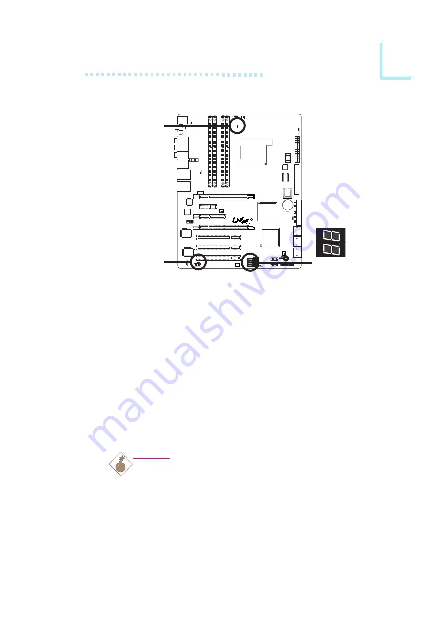
LEDs

DRAM Power LED

This LED will light when the system’s power is on.

Standby Power LED

This LED will light when the system is in the standby mode.

Debug LED

The Debug LED displays POST codes. POST (Power-On Self Tests)
which is controlled by the BIOS is performed whenever you power-
on the system. POST will detect the status of the system and its
components. Each code displayed on the LED corresponds to a cer-
tain system status.

Warning:

When the DRAM Power LED and/or Standby Power LED lit red,
it indicates that power is present on the DDR2 sockets and/or
PCI slots. Power-off the PC then unplug the power cord prior to
installing any memory modules or add-in cards. Failure to do so
will cause severe damage to the motherboard and components.

Standby

Power LED

DRAM

Power LED

Debug LED

.

.

.

.

.

.

.

.

Содержание LanParty UT NF590 SLI-M2R/G

Страница 1: ...System Board User s Manual 935 N59SM1 000G 92210629 ...

Страница 2: ...r use of this manual and specifically disclaims any express or implied warranties of merchantability or fitness for any particular purpose The user will assume the entire risk of the use or the results of the use of this document Further the manufacturer reserves the right to revise this publication and make changes to its contents at any time without obligation to notify any person or entity of s...

Страница 3: ...rticular installation If this equipment does cause harmful interference to radio or television reception which can be determined by turning the equipment off and on the user is encouraged to try to correct the interference by one or more of the following measures Reorient or relocate the receiving antenna Increase the separation between the equipment and the receiver Connect the equipment into an ...

Страница 4: ...pter 2 Hardware Installation System Board Layout System Memory CPU Jumper Settings Rear Panel I O Ports Internal I O Connectors Chapter 3 BIOS Setup Award BIOS Setup Utility RAID BIOS Updating the BIOS Chapter 4 Supported Softwares Chapter 5 Cool n Quiet Technology Chapter 6 RAID Chapter 7 SLI Technology Appendix A System Error Message Appendix B Troubleshooting 5 5 6 8 8 9 9 10 10 12 17 19 21 23 ...

Страница 5: ...ponents and product specifications 2 The warranty is void if the product has been subjected to physical abuse improper installation modification accidents or unauthorized repair of the product 3 Unless otherwise instructed in this user s manual the user may not under any circumstances attempt to perform service adjustments or repairs on the product whether in or out of warranty It must be returned...

Страница 6: ...unts and or promotional offers and puts your licensing information on file so that we may efficiently assist you if in any case needed Please follow the steps below to access the product registration page 1 Run Internet Explorer then type www dfi com tw in the Address bar On DFI s homepage click Global or the language of your choice 2 Click the Support menu then select Product Register Service ...

Страница 7: ...ntroduction 7 3 The DFI Product Registration page will appear Click Next to continue 4 Select or fill in the necessary information to complete the registration 5 Thank you for registering your DFI product ...

Страница 8: ...tant Electrostatic discharge ESD can damage your processor disk drive and other components Perform the upgrade instruction procedures described at an ESD workstation only If such a station is not available you can provide some ESD protection by wearing an antistatic wrist strap and attaching it to a metal part of the system chassis If a wrist strap is unavailable establish and maintain contact wit...

Страница 9: ...ssories in the package may not come similar to the information listed above This may differ in accordance to the sales region or models in which it was sold For more information about the standard package in your region please contact your dealer or sales representative Before Using the System Board Before using the system board prepare basic system components If you are installing the system boar...

Страница 10: ...full speed x16 lanes Use identical SLI ready PCI Express x16 graphics cards 1 PCI Express x1 slot 1 PCI Express x8 slot 3 PCI slots Award BIOS CMOS Reloaded CPU DRAM overclocking CPU DRAM Chipset overvoltage 4Mbit flash memory ACPI and OS Directed Power Management ACPI STR Suspend to RAM function Wake On PS 2 Keyboard Mouse Wake On LAN RTC timer to power on the system AC power failure recovery Mon...

Страница 11: ...e port 1 mini DIN 6 PS 2 keyboard port 2 S PDIF RCA jacks S PDIF in and S PDIF out Karajan audio module 6 audio jacks 1 IEEE 1394 port 2 RJ45 LAN ports 6 USB 2 0 1 1 ports 2 connectors for 4 additional external USB 2 0 1 1 ports 1 connector for 1 external IEEE 1394 port 1 connector for 1 external serial port 1 connector for the Karajan audio module 1 front audio connector for external line out and...

Страница 12: ...tively lowers power consumption by lowering its CPU speed and voltage subsequently decreasing its noise level The NVIDIA SLITM Scalable Link Interface technology connects two SLI ready PCI Express graphics cards in a single and scalable system The two identical graphics cards which are connected via the SLI bridge will pro vide extreme performance allowing you to enjoy games with the most visual e...

Страница 13: ...k at 1 8V supply compared to 2 6V memory voltage for DDR modules DDR2 also incorporates new innovations such as the On Die Termination ODT as well as larger 4 bit pre fetch against DDR which fetches 2 bits per clock cycle CMOS Reloaded is a technology that allows storing multiple user defined BIOS settings by using the BIOS utility to save load and name the settings This is especially useful to ov...

Страница 14: ...like CD recorders Serial ATA is a storage interface that is compli ant with SATA 1 0 specification NVIDIA MCP55PXE and Silicon Image SiI 3132 both support speed of up to 3Gb s Serial ATA improves hard drive performance faster than the standard parallel ATA whose data transfer rate is 100MB s The NVIDIA MCP55PXE chip allows configuring RAID on Serial ATA drives It supports RAID 0 RAID 1 RAID 0 1 an...

Страница 15: ... at a distance of 1 meter The system board supports USB 2 0 and USB 1 1 ports USB 1 1 supports 12Mb second bandwidth while USB 2 0 supports 480Mb second bandwidth providing a marked improvement in device transfer speeds between your computer and a wide range of simultaneously accessible external Plug and Play peripherals This feature allows the network to remotely wake up a Soft Power Down Soft Of...

Страница 16: ... power off the system at once by pressing the power button or selecting Standby when you shut down Windows 2000 XP without having to go through the sometimes tiresome process of closing files applications and operating system This is because the system is capable of storing all programs and data files during the entire operating session into RAM Random Access Memory when it powers off The operatin...

Страница 17: ...16 de SLI prêtes identiques 1 slot PCI Express x1 1 slot PCI Express x8 3 slots PCI Compatible avec Award BIOS CMOS Reloaded Overclocking de CPU DRAM Contrôle du voltage de CPU DRAM Chipset Mémoire Flash 4Mbit ACPI et OS Directed Power Management ACPI STR Suspend to RAM fonction Réveil Sur PS 2 Clavier Souris Eveil Sonnerie Minuterie RTC pour allumer le système Récupération après Défaillance d Ali...

Страница 18: ...r PS 2 2 S PDIF RCA prises S PDIF in et S PDIF out 1 carte Karajan 6 prises audio 1 port IEEE 1394 2 ports RJ45 LAN 6 ports USB 2 0 1 1 2 connecteurs pour 4 ports USB 2 0 1 1 supplémentaires 1 connecteur pour 1 IEEE 1394 1 connecteur pour 1 série 1 connecteur pour module audio Karajan 1 connecteur audio frontal pour les jacks de sortie externe et d entrée micro sur le module audio Karajan 1 connec...

Страница 19: ...plätzen 3 PCI Einbauplätzen Kompatibilität mit Award BIOS CMOS Reloaded Die Frequenzerhöhung CPU DRAM Spannungserhöhung CPU DRAM Chipset Flash Speicher 4Mbit ACPI und OS Directed Power Management ACPI STR Suspend to RAM funktion Wecken bei Betätigung der PS 2 Tastatur Maus Wecken des Systems durch das Netzwerk RTC Taktgeber zum Einschalten des Systems Wiederherstellung der Wechselstromversorgung n...

Страница 20: ...schlüsse S PDIF in und S PDIF out Karajan platine 6 Audio Anschlußbuchsen 1 IEEE 1394 Anschlüsse 2 RJ45 LAN Anschlüsse 6 USB 2 0 1 1 Anschlüsse 2 Anschlußfassung für 4 zusätzliche externe USB 2 0 1 1 Anschlüsse 1 Anschluß für eine externe IEEE 1394 Schnittstelle 1 Anschluß für eine externe serieller DB 9 Anschluß 1 Anschluß für eine Karajan Audiomodul 1 Front Audioanschluss für externe Mikrofon Ei...

Страница 21: ...xpress x1 1 slot PCI Express x8 3 slots PCI Award BIOS CMOS Reloaded Subida de frecuencia de CPU DRAM Subida de voltaje de CPU DRAM Chipset Memoria Instante 4Mbitios ACPI y OS Directed Power Management ACPI STR Suspend to RAM función PS 2 Teclado Ratón de Wake On Wake On LAN Temporizador de RTC para encender el sistema Recuperación de Fracaso de Energía AC Monitores de los CPU sistema chipset temp...

Страница 22: ... S PDIF out 1 tablero de Karajan 6 enchufes de audio 1 puerto de IEEE 1394 y 2 puertos de RJ45 LAN 6 puertos de USB 2 0 1 1 2 conectores para 4 puertos de USB 2 0 1 1 externo adicional 1 conector para un puerto de IEEE 1394 1 conector para un puerto de DB 9 serie externa 1 conector para un módulo de sonido de Karajan 1 connector de sonido delantera por linea externa y micrófono interno en el módul...

Страница 23: ...8 è x16 DIMM Ïîääåðæèâàåò íåáóôô DIMM 2 PCI Express x16 ñëîòîâ Ðåæèì SLI èëè Ðåæèì îäíîãî VGA Ïðîïóñêíàÿ ñïîñîáíîñòü êàæäîãî ñëîòà ñîñòàâëÿåò x16 2 âèäåîêàðòû SLI ready èñïîëüçóéòå îäèíàêîâûå ïëàòû íà ñëîòàõ PCI Express x16 1 PCI Express x1 ñëîòîâ 1 PCI Express x8 ñëîòîâ 3 PCI ñëîòîâ Award BIOS CMOS Reloaded Ïîâûøåíèå àñòîòû CPU DRAM Ïîâûøåíèå íàïðÿæåíèÿ CPU DRAM Chipset 4Mbit Flash Ïàìÿòü ACPI è ...

Страница 24: ...ííûõ Silicon Image Sil 3132 Ñêîðîñòü SATA äî 3 ÃÁ ñ RAID 0 RAID 1 è RAID 0 1 VIA VT6307 Ïîääåðæèâàåò 2 100 200 400 Mb sec ïîðòà 1 ìèíè DIN 6 PS 2 ïîðò äëÿ ìûøè è 1 ìèíè DIN 6 PS 2 ïîðò äëÿ êëàâèàòóðû 2 S PDIF RCA çâóêà S PDIF in è S PDIF out çâóêîâîé ìîäóëü Karajan 6 ãíåçäà äëÿ çâóêà 1 IEEE 1394 ïîðò è 2 RJ45 LAN ïîðò 6 USB 2 0 1 1 ïîðòà 2 ðàçúåì äëÿ 4 õ äîïîëíèòåëüíûõ âíåøíèõ USB 2 0 1 1 ïîðòîâ 1...

Страница 25: ...25 1 Introduction 1 ...

Страница 26: ...26 Introduction 1 ...

Страница 27: ...27 2 Hardware Installation System Board Layout Chapter 2 Hardware Installation ...

Страница 28: ...mponents Perform the upgrade instruction procedures described at an ESD workstation only If such a station is not available you can provide some ESD protection by wearing an antistatic wrist strap and attaching it to a metal part of the system chassis If a wrist strap is unavailable establish and maintain contact with the system chassis throughout any procedures requiring ESD protection The system...

Страница 29: ...hannel provides better system performance because it doubles the data transfer rate BIOS Setting Configure the system memory in the Genie BIOS Setting submenu DRAM Configuration section of the BIOS DIMMs are on the same channel DIMMs in a channel can be identical or completely different However we highly recommend using identical DIMMs Not all slots need to be populated DIMMs of the same memory co...

Страница 30: ...ust correspond with Pin 1 of the socket 1 Pull the tabs which are at the ends of the socket to the side 2 Position the DIMM above the socket with the notch in the module aligned with the key on the socket 3 Seat the module vertically into the socket Make sure it is completely seated The tabs will hold the DIMM in place Pin 1 Notch Key Tab Tab ...

Страница 31: ...uipped with Socket AM2 for installing an AMD CPU designed for this socket Installing the CPU 1 Make sure the PC and all other peripheral devices connected to it has been powered down 2 Disconnect all power cords and cables 3 Locate Socket AM2 on the system board X ...

Страница 32: ...ocket refer to the en larged image shown below Important Handle the CPU by its edges and avoid touching the pins 4 Unlock the socket by pushing the lever sideways away from the socket then lifting it up to a 90o angle Make sure the lever is lifted to at least this angle otherwise the CPU will not fit in properly Gold mark Lever ...

Страница 33: ... easily be inserted without exerting any force Important Do not force the CPU into the socket Forcing the CPU into the socket may bend the pins and damage the CPU 7 Once the CPU is in place push down the lever to lock the socket The lever should click on the side tab to indicate that the CPU is completely secured in the socket Side tab ...

Страница 34: ...ink The fan and heat sink package usually contains the fan and heat sink assembly and an installation guide If the installa tion procedure in the installation guide differs from the one in this section please follow the installation guide in the package 1 Before you install the fan heat sink you must apply a thermal paste onto the top of the CPU The thermal paste is usually supplied when you purch...

Страница 35: ...on the retention clip into the retaining tab s of the reten tion module base Hook the other side of the retention clip so that the hole s on the retention clip also fit into the retaining tab s of the retention module base Retaining tab Retention module base 2 The system board comes with the retention module base already installed Retaining tab Retention clip ...

Страница 36: ...e retention module base 2 Make sure there is sufficient air circulation across the CPU fan and heat sink 5 Connect the CPU fan s cable connector to the CPU fan connec tor on the system board 4 Move the retention lever to its opposite side then push it down to lock the fan and heat sink assembly to the retention module base Retention lever ...

Страница 37: ...ored in the ROM BIOS To load the default values stored in the ROM BIOS please follow the steps below 1 Power off the system and unplug the power cord 2 Set JP2 pins 2 and 3 to On Wait for a few seconds and set JP2 back to its default setting pins 1 and 2 On 3 Now plug the power cord and power on the system If your reason for clearing the CMOS data is due to incorrect setting of the processor s rat...

Страница 38: ...BIOS Setting submenu and press Enter 6 Set the processor s clock ratio to its default setting or an appro priate setting Refer to the Genie BIOS Setting section in chapter 3 for more information 7 Press Esc to return to the main menu of the BIOS setup utility Select Save Exit Setup and press Enter 8 Type Y and press Enter ...

Страница 39: ...use port Selecting 5VSB will allow you to use the PS 2 keyboard or PS 2 mouse to wake up the system BIOS Setting Configure the PS 2 keyboard mouse wake up function in the Integrated Peripherals submenu of the BIOS Refer to chapter 3 for more information Important The 5VSB power source of your power supply must support 720mA 1 3 2 1 3 2 ...

Страница 40: ...use the USB keyboard or USB mouse to wake up the system Important If you are using the Wake On USB Keyboard Mouse function for 2 USB ports the 5VSB power source of your power supply must support 1 5A For 3 or more USB ports the 5VSB power source of your power supply must support 2A 2 3 On 5VSB 1 2 On 5V default 1 3 2 1 3 2 2 3 On 5VSB 1 2 On 5V default 1 3 2 1 3 2 ...

Страница 41: ...PC s speaker By default the buzzer is on allowing you to hear the system s beep messages and warnings If you intend to use an external speaker turn this function off by setting JP8 pins 1 and 2 to On Speaker On Off Select X JP8 2 3 On Speaker On default 1 2 On Speaker Off Buzzer 3 1 2 3 1 2 ...

Страница 42: ...the system 1 Power off the system and unplug the power cord 2 Set JP1 pins 2 and 3 to On Wait for a few seconds then set JP1 back to its default setting pins 1 and 2 On 3 Plug the power cord and power on the system The system will reboot normally without losing all data stored in the CMOS Safe Boot X JP1 2 3 On Safe boot 1 2 On Default ...

Страница 43: ...arajan audio module Line in jack Front right left jack Line out Mic in jack Center Subwoofer jack Rear right left port jack Side right left port jack 1394 1 port 6 USB ports 2 LAN Gigabit Phy ports PS 2 Mouse PS 2 K B S PDIF in S PDIF out Line in Front R L Line out Mic in Center Subwoofer Rear R L Side R L 1394 1 USB 1 2 USB 3 4 USB 5 6 LAN LAN Karajan audio module ...

Страница 44: ... your computer prior to connecting or disconnecting a mouse or keyboard Failure to do so may damage the system board Wake On PS 2 Keyboard Mouse The Wake On PS 2 Keyboard Mouse function allows you to use the PS 2 keyboard or PS 2 mouse to power on the system To use this function Jumper Setting JP7 must be set to 2 3 On 5VSB Refer to PS 2 Power Select in this chapter for more information BIOS Setti...

Страница 45: ... connect optical S PDIF ports The S PDIF ports may be mounted on a card edge bracket Install the card edge bracket to an available slot at the rear of the system chassis then connect the audio cable connector to J3 Make sure pin 1 of the audio cable connector is aligned with pin 1 of J3 Important DO NOT use optical S PDIF and coaxial RCA S PDIF at the same time W Optical S PDIF 1 5 5V Key SPDIF ou...

Страница 46: ...L Karajan Audio Module Karajan audio connector Karajan audio module Installing the Karajan Audio Module The system board package includes a Karajan audio module and the module holder The module holder is used to stabilize the Karajan audio module onto the system board Plug Plug Karajan audio module Module holder ...

Страница 47: ...ough to the bottom of the system board While at it the 14 pin connector at the solder side of the module must also insert into the Karajan audio connector at location J7 of the system board Make sure the plugs snap firmly out the bottom of the board 1 Fit the module holder onto the Karajan audio module Mounting holes Karajan audio connector J7 ...

Страница 48: ... out Lime This jack is used to connect to the front right and front left speakers of the audio system Mic in Jack Pink This jack is used to connect an external microphone Center Subwoofer Jack Orange This jack is used to connect to the center and subwoofer speakers of the audio system Rear Right Left Jack Black This jack is used to connect to the rear right and rear left speakers of the audio syst...

Страница 49: ...u dio s line out and mic in functions Audio codec 1 1 Line in Front R L Mic in Center Subwoofer Rear R L Side R L X 1 2 10 9 Mic_Left GND Mic_Right Vcc Line out_Right N C N C Line out_Left Line out_Left_Front Remove the jumper caps from pins 5 6 and pins 9 10 of J4 prior to connecting the front audio cable connector Make sure pin 1 of the cable connector is aligned with pin 1 of J4 If you are not ...

Страница 50: ...ting an additional 1394 device The 1394 port may come mounted on a card edge bracket Install the card edge bracket to an available slot at the rear of the system chassis then insert the connector that is attached to the 1394 port cable to J8 Make sure pin 1 of the cable connector is aligned with pin 1 of the J8 IEEE 1394 Ports W W 1394 2 1394 1 12V fused 1 TPA Ground TPB 12V fused Key TPA Ground T...

Страница 51: ...J18 USB 7 8 and J33 USB 9 10 connectors allow you to connect 4 additional USB 2 0 1 1 ports The USB ports may come mounted on a card edge bracket Install the card edge bracket to an available slot at the rear of the system chassis then insert the con nector that is attached to the USB port cables to J18 or J33 BIOS Setting Configure the onboard USB in the Integrated Peripherals submenu of the BIOS...

Страница 52: ...board Mouse The Wake On USB Keyboard Mouse function allows you to use a USB device to wake up a system from the S3 STR Suspend To RAM state To use this function Jumper Setting JP5 and or JP6 must be set to 2 3 On 5VSB Refer to USB Power Select in this chapter for more information Important If you are using the Wake On USB Keyboard Mouse function for 2 USB ports the 5VSB power source of your power ...

Страница 53: ... the system board to connect to a local area network by means of a network hub BIOS Setting Configure the onboard LAN in the Genie BIOS Setting submenu PCI Device Control submenu of the BIOS Refer to chapter 3 for more information Driver Installation Install the LAN driver Refer to chapter 4 for more information W W LAN LAN ...

Страница 54: ... in Front R L Mic in Center Subwoofer Rear R L Side R L X CD in Internal Audio Connector The CD in J2 connector on the Karajan audio module is used to receive audio from a CD ROM drive TV tuner or MPEG card 1 4 Right audio channel Left audio channel Ground Ground ...

Страница 55: ... with pin 1 of the header Connecting the Floppy Disk Drive Cable Install one end of the floppy disk drive cable into the shrouded floppy disk header J23 on the system board and the other end most connector to the drive you want to designate as Drive A If you are connecting another drive Drive B install the middle connector of the cable to the drive The colored edge of the daisy chained ribbon cabl...

Страница 56: ...e other end to your Serial ATA device BIOS Setting Configure Serial ATA in the Genie BIOS Setting submenu PCI De vice Control RAID Config section of the BIOS Refer to chapter 3 for more information Configuring RAID The system board allows configuring RAID on Serial ATA drives Refer to chapter 6 for steps in configuring RAID Six Serial ATA ports supported by the NVIDIA MCP55PXE chip SATA 5 6 SATA 3...

Страница 57: ...l ATA connec tor and the other end to your Serial ATA device BIOS Setting Configure Serial ATA in the Genie BIOS Setting submenu PCI De vice Control section of the BIOS Refer to chapter 3 for more information Configuring RAID The system board allows configuring RAID on Serial ATA drives Refer to chapter 6 for steps in configuring RAID SATA 8 J21 SATA 7 J20 X 1 7 GND TXP TXN GND RXN RXP GND 1 7 GND...

Страница 58: ...ed with pin 1 of the header Each IDE connector supports 2 devices a Master and a Slave Use an IDE ribbon cable to connect the drives to the system board An IDE ribbon cable have 3 connectors on them one that plugs into an IDE connector on the system board and the other 2 connects to IDE devices The connector at the end of the cable is for the Master drive and the connector in the middle of the cab...

Страница 59: ...ATA 133 hard drives We recommend that you use hard drives from the same manufacturer In a few cases drives from two different manufacturers will not function properly when used together The problem lies in the hard drives not the system board Important If you encountered problems while using an ATAPI CD ROM drive that is set in Master mode please set the CD ROM drive to Slave mode Some ATAPI CD RO...

Страница 60: ...to an available bracket slot at the rear of the system chassis Make sure the colored stripe on the ribbon cable is aligned with pin 1 of the connector The serial port is an RS 232 asynchronous communication port with 16C550A compatible UARTs that can be used with modems serial printers remote display terminals and other serial devices BIOS Setting Configure the serial port in the Integrated Periph...

Страница 61: ...stem board Make sure to connect the cable connector to the IrDA CIR connector according to their pin functions BIOS Setting Configure IrDA CIR in the Integrated Peripherals submenu of the BIOS Driver Installation You may need to install the proper drivers in your operating system to use the IrDA CIR function Refer to your operating system s manual or documentation for more information 1 5 VCC N C ...

Страница 62: ...ing fans will provide adequate airflow throughout the chassis to prevent overheating the CPU and system board components BIOS Setting The PC Health Status submenu of the BIOS will display the current speed of the cooling fans Refer to chapter 3 for more information X X Fan 5 X X CPU fan Fan 2 Fan 4 Fan 3 1 3 Ground Power Sense X 3 1 Ground Power N C 1 3 Ground Power N C 1 3 Ground Power Sense 4 1 ...

Страница 63: ...wer on the system POST will detect the status of the system and its components Each code displayed on the LED corresponds to a cer tain system status Warning When the DRAM Power LED and or Standby Power LED lit red it indicates that power is present on the DDR2 sockets and or PCI slots Power off the PC then unplug the power cord prior to installing any memory modules or add in cards Failure to do ...

Страница 64: ...C 3 3VDC COM 5VDC COM 5VDC COM PWR_OK 5VSB 12VDC 12VDC 3 3VDC 3 3VDC 12VDC COM PS_ON COM COM COM NC 5VDC 5VDC 5VDC COM 24 pin ATX Your power supply unit may come with an 8 pin or 4 pin 12V power connector The 12V power enables the delivery of more 12VDC current to the processor s Voltage Regulator Module VRM If available it is preferable to use the 8 pin power otherwise connect a 4 pin power conne...

Страница 65: ...ty to the entire system The system board will still work even if the additional power connector is not connected The system board requires a minimum of 300 Watt power supply to operate Your system configuration CPU power amount of memory add in cards peripherals etc may exceed the minimum power requirement To ensure that adequate power is provided we strongly recommend that you use a minimum of 40...

Страница 66: ...ompliant with a 24 pin ATX main power connector dual 12V rails 12V1 and 12V2 and an 8 pin EPS server style 12V power connector The 12V power connector enables the delivery of more 12VDC current to the processor s Voltage Regulator Module VRM It is preferable to use the 8 pin power rather than the usual 4 pin power connect to CN9 as shown below High End 7900GTX 500 Watt w min 12V 30A Mid Range 6800...

Страница 67: ... 4 pin 12V power connector The 12V power connector enables the delivery of more 12VDC current to the processor s Voltage Regulator Module VRM If available it is preferable to use the 8 pin power otherwise connect the 4 pin power connector to CN9 as shown below Connect the 4 pin power to CN9 High End 7900GTX 480 Watt w min 12V 24A Mid Range 6800GT 450 Watt w min 12V 22A Entry Level 6600GT 400 Watt ...

Страница 68: ... system s configuration such as the wattage of the power supply the sequence of the supplied power as well as the number of peripheral devices connected to the system Due to this reason we strongly recommend that you wait for the Standby Power LED refer to the LEDs section in this chapter for the location of the Standby Power LED to lit off 2 After the Standby Power LED has lit off wait for 6 seco...

Страница 69: ...hus prolonging the life of the power supply or system SPEAKER Speaker Connector This connects to the speaker installed in the system chassis ATX SW ATX Power Switch Depending on the setting in the BIOS setup this switch is a dual function power button that will allow your system to enter the Soft Off or Suspend mode Refer to Soft Off By PBTN in the Power Management Setup Chapter 3 X J19 1 2 19 20 ...

Страница 70: ...n it may indicate that the CPU or memory module was not installed properly Please make sure they are properly inserted into their corresponding socket Pin 3 5 14 16 8 10 18 20 7 9 13 15 17 19 2 4 6 HD LED Primary Secondary IDE LED Reserved ATX SW ATX power switch Reserved RESET Reset switch SPEAKER Speaker connector PWR LED Power Standby LED Pin Assignment HDD LED Power HDD N C N C PWRBT PWRBT N C...

Страница 71: ... power switch and reset switch on the system board are user friendly especially to DIY users They provide convenience in powering on and or resetting the system while fine tuning the system board before it is installed into the system chassis Reset Switch Power Switch ...

Страница 72: ...stall a graph ics card into the x16 slot align the graphics card above the slot then press it down firmly until it is completely seated in the slot The retaining clip of the slot will automatically hold the graphics card in place Refer to chapter 7 for information on configuring SLI PCI Express x1 x8 Install PCI Express x1 x8 cards such as network cards or other cards that comply to the PCI Expres...

Страница 73: ...t is an auxiliary source of power when the main power is shut off Safety Measures Danger of explosion if battery incorrectly replaced Replace only with the same or equivalent type recommend by the manufacturer Dispose of used batteries according to the battery manufacturer s instructions Battery ...

Страница 74: ...he screen Press DEL to enter setup If the message disappears before you respond restart the system or press the Reset button You may also restart the system by press ing the Ctrl Alt and Del keys simultaneously When you press Del the main menu screen will appear Chapter 3 BIOS Setup Phoenix AwardBIOS CMOS Setup Utility X Genie BIOS Setting X CMOS Reloaded Load Optimized Defaults Set Supervisor Pas...

Страница 75: ...d CMOS Features Use the arrow keys to highlight Standard CMOS Features and press Enter A screen similar to the one below will appear Date mm dd yy Time hh mm ss X Primary IDE Master X Primary IDE Slave X Internal Phy SATA 1 X Internal Phy SATA 2 X Internal Phy SATA 3 X Internal Phy SATA 4 X Internal Phy SATA 5 X Internal Phy SATA 6 Drive A Halt On Base Memory Extended Memory Total Memory Phoenix A...

Страница 76: ...6 will appear only if the Serial ATA Controller field is set to Enabled This field is in the Genie BIOS Setting PCI Device Control RAID Config section of the BIOS IDE HDD Auto Detection Primary IDE Master Access Mode Capacity Cylinder Head Precomp Landing Zone Sector Phoenix AwardBIOS CMOS Setup Utility Primary IDE Master Item Help Menu Level XX To auto detect the HDD s size head on this channel M...

Страница 77: ...uire that you select CHS or Large Please check your operating system s manual or Help desk on which one to select Capacity Displays the approximate capacity of the disk drive Usually the size is slightly greater than the size of a formatted disk given by a disk checking program Cylinder This field displays the number of cylinders Head This field displays the number of read write heads Precomp This...

Страница 78: ...he cursor to a field then press Enter The following screen will appear Press Enter Auto Auto 0 MB 0 0 0 0 0 IDE Auto Detection Detects the parameters of the drive The parameters will automati cally be shown on the screen Extended IDE Drive The default is Auto The BIOS will automatically detect the Serial ATA drives Access Mode For hard drives larger than 528MB you would typically select the LBA ty...

Страница 79: ...lays the number of read write heads Precomp This field displays the number of cylinders at which to change the write timing Landing Zone This field displays the number of cylinders specified as the landing zone for the read write heads Sector This field displays the number sectors per track ...

Страница 80: ...d All Errors The system boot will stop whenever the BIOS detects a non fatal error All But Keyboard The system boot will not stop for a key board error it will stop for all other errors All But Diskette The system boot will not stop for a disk er ror it will stop for all other errors All But Disk Key The system boot will not stop for a disk or keyboard error it will stop for all other er rors Base...

Страница 81: ... be identical to this one X Removable Device Priority X Hard Disk Boot Priority First Boot Device Second Boot Device Third Boot Device Boot Other Device Security Option MPS Version Control For OS OS Select For DRAM 64MB Full Screen LOGO Show Phoenix AwardBIOS CMOS Setup Utility Advanced BIOS Features Item Help Menu Level X Select Removable Boot Device Priority Press Enter Press Enter Removable Har...

Страница 82: ... to move it down the list The settings on the screen are for reference only Your version may not be identical to this one F5 Previous Values F6 Fail Safe Defaults F7 Optimized Defaults Phoenix AwardBIOS CMOS Setup Utility Removable Device Priority Item Help Menu Level XX Use or to select a device then press to move it up or to move it down the list Press ESC to exit this menu Move PU PD Change Pri...

Страница 83: ...e it down the list The settings on the screen are for reference only Your version may not be identical to this one Phoenix AwardBIOS CMOS Setup Utility Hard Disk Boot Priority Item Help Menu Level XX Use or to select a device then press to move it up or to move it down the list Press ESC to exit this menu Move PU PD Change Priority F10 Save ESC Exit F5 Previous Values F6 Fail Safe Defaults F7 Opti...

Страница 84: ...rd in the Set Supervisor User Password submenu System The system will not boot and access to Setup will be denied unless the correct password is entered at the prompt Setup The system will boot but access to Setup will be denied unless the correct password is entered at the prompt MPS Version Control for OS This field is used to select the MPS version that the system board is using OS Select for D...

Страница 85: ...would be if you discovered some incompatibility or that data was being lost while using your system PMU The options are Auto and Disabled SSE SSE2 SSE3 Instructions The options are Enabled and Disabled NVIDIA GPU Ex The options are Auto and Disabled The settings on the screen are for reference only Your version may not be identical to this one Phoenix AwardBIOS CMOS Setup Utility Advanced Chipset ...

Страница 86: ...n Onboard FDC Controller Onboard Serial Port Onboard IRDA Select IR Mode Select UR2 Deplex Mode CIR Port Address x CIR Port IRQ Press Enter PCIEx Slave V1 1 V2 0 SHADOW Disabled BUTTON ONLY Enter Ctrl F1 Enabled Disabled Auto IrDA Half Disabled 11 Primary IDE Primary Master PIO Primary Slave PIO Primary Master UDMA Primary Slave UDMA IDE DMA Transfer Access IDE Prefetch Mode Phoenix AwardBIOS CMOS...

Страница 87: ...lly set the system according to your hard disk drive s timing Mode 0 4 You can select a mode that matches your hard disk drive s timing Caution Do not use the wrong setting or you will have drive errors Primary Master UDMA and Primary Slave UDMA These fields allow you to set the Ultra DMA in use When Auto is selected the BIOS will select the best available option after checking your hard drive or ...

Страница 88: ...Memory Type This field is used to select the memory allocated for USB The op tions are Shadow and Base Memory 640K USB KB Storage Support If you are using a USB keyboard or USB storage under DOS set this field to Enabled Due to the limited space of the BIOS ROM the support for legacy USB keyboard in DOS mode is by default set to Disabled With more BIOS ROM space available it will be able to suppor...

Страница 89: ... When this option is selected press the wake up key of the Windows 98 compatible key board to power on the system KB Power On Password Move the cursor to this field and press Enter Enter your password You can enter up to 5 characters Type in exactly the same password to confirm then press Enter The power button will not function once a keyboard password has been set in this field You must type the...

Страница 90: ...evice Disabled Disables the onboard IrDA IR Mode Select This field is used to select the type of IrDA standard supported by your IrDA device For better transmission of data your IrDA periph eral device must be within a 30o angle and within a distance of 1 meter UR2 Duplex Mode Half Data is completely transmitted before receiving data Full Transmits and receives data simultaneously CIR Port Address...

Страница 91: ...uspend mode S1 POS Enables the Power On Suspend function S3 STR Enables the Suspend to RAM function The settings on the screen are for reference only Your version may not be identical to this one Phoenix AwardBIOS CMOS Setup Utility Power Management Setup Item Help Menu Level X Move Enter Select F1 General Help PU PD Value F10 Save ESC Exit F5 Previous Values F6 Fail Safe Defaults F7 Optimized Def...

Страница 92: ...election will cause the system to turn off the vertical and horizontal synchroniza tion ports and write blanks to the video buffer Blank Screen This option only writes blanks to the video buffer DPMS Support Initializes display power management signaling Use this option if your video board supports it HDD Power Down This is selectable only when the Power Management field is set to User Define When...

Страница 93: ... off the system Instant Off Pressing and then releasing the power button at once will immediately power off your system WOL PME From Soft Off Set this field to Enabled to wake up the system via the onboard LAN or via a LAN card that uses the PCI PME Power Manage ment Event signal to remotely wake up the system Access to the LAN card will cause the system to wake up Refer to the card s documentatio...

Страница 94: ...power on The system will power on on the set date and time set in the Time hh mm ss Alarm field Time hh mm ss of Alarm This is used to set the time you would like the system to power on PWRON After PWR Fail Off When power returns after an AC power failure the sys tem s power is off You must press the Power button to power on the system On When power returns after an AC power failure the sys tem wi...

Страница 95: ... Auto ESCD The system will automatically detect the settings for you Manual Choose the specific IRQ in the IRQ Resources field The settings on the screen are for reference only Your version may not be identical to this one Phoenix AwardBIOS CMOS Setup Utility PnP PCI Configurations Item Help Menu Level X Move Enter Select F1 General Help PU PD Value F10 Save ESC Exit F5 Previous Values F6 Fail Saf...

Страница 96: ...esources Item Help Menu Level XX Move Enter Select F1 General Help PU PD Value F10 Save ESC Exit F5 Previous Values F6 Fail Safe Defaults F7 Optimized Defaults IRQ 5 assigned to IRQ 7 assigned to IRQ 9 assigned to IRQ 10 assigned to IRQ 11 assigned to IRQ 14 assigned to IRQ 15 assigned to PCI Device PCI Device PCI Device PCI Device PCI Device PCI Device PCI Device Legacy ISA for devices compliant ...

Страница 97: ...you want to reduce the CPU fan s noise or prevent CPU overheat select a lower temperature in the CPUFan Fully On If CPUTemp field to allow the CPU fan to rotate full speed at the selected lower temperature The settings on the screen are for reference only Your version may not be identical to this one Phoenix AwardBIOS CMOS Setup Utility PC Health Status Item Help Menu Level X Move Enter Select F1 ...

Страница 98: ... temperature NB Fan Fully On If NB Temp This field is used to select the north bridge chip s temperature that would allow the chip s fan to rotate at full speed NB Fan Turn Off If NB Temp This field is used to select the north bridge chip s temperature that would allow the chip s fan to rotate at a start speed which is the slowest speed Note If the north bridge chip s temperature runs between the ...

Страница 99: ...ect F1 General Help PU PD Value F10 Save ESC Exit F5 Previous Values F6 Fail Safe Defaults F7 Optimized Defaults The settings on the screen are for reference only Your version may not be identical to this one PCI Device Control Voltage Control DRAM Configuration Refer to the following pages for more informa tion on these submenus CPU Clock Multiplier This field is used to select the operating CPU ...

Страница 100: ...used to select the Northbridge to Southbridge HT width PCI E Slot4 Clock This field is used to select the clock of PCIE 4 PCI E Slot1 Clock This field is used to select the clock of PCIE 1 CPU CoreVoltage This field will show the CPU s current voltage HT LinkVoltage This field will show the HT Link s current voltage SB Core Voltage This field will show the Southbridge s current voltage DRAM Voltag...

Страница 101: ...PU PD Value F10 Save ESC Exit F5 Previous Values F6 Fail Safe Defaults F7 Optimized Defaults Disabled Auto Auto Auto SATA RAID 5 RAID Config Please refer to the following pages for more information on this submenu HD Audio Auto The system automatically detects the onboard High Definition audio CODEC Disabled Disables the onboard audio Disable the onboard audio when using an audio PCI card MAC LAN ...

Страница 102: ...102 3 BIOS Setup SiI3132 SATA RAID Control This field is used to configure the Serial ATA ports supported by the Silicon Image SiI3132 chip ...

Страница 103: ...SATA 4 on the system board SATA 3 Primary RAID and SATA 3 Secondary RAID These fields are used to enable or disable the RAID function of SATA 3 s primary and or secondary channel SATA 5 and SATA 6 on the system board RAID Config The settings on the screen are for reference only Your version may not be identical to this one Serial ATA Controller RAID Enable SATA 1 Primary RAID SATA 1 Secondary RAID...

Страница 104: ...vious Values F6 Fail Safe Defaults F7 Optimized Defaults Auto 0 1 20V 1 50V 1 50V Low Low Auto Auto 63 CPU VID Control This field allows you to manually adjust to a higher core voltage that is supplied to the CPU If you want to use the CPU s default core voltage leave this field in its default setting The CPU s Vcore will be generated according to the CPU VID configuration Important Although this ...

Страница 105: ...C51 HT driving strength CPU C51 HT Voltage This field is used to select the CPU C51 HT voltage C51 MCP55 HT Voltage This field is used to select the C51 MCP55 HT voltage DRAM Voltage Control This field allows you to manually select higher voltage supplied to the DRAM If you want to use the DRAM s default voltage leave this field in its default setting Important Although this function is supported ...

Страница 106: ...Help Menu Level XX Drive Strength setting for DRAM Interface Move Enter Select F1 General Help PU PD Value F10 Save ESC Exit F5 Previous Values F6 Fail Safe Defaults F7 Optimized Defaults Press Enter Press Enter Skip DQS Enabled Per Channel Disabled Enabled Enabled E0 Memory Drive Strength Memory Timings DQS Training Control The options are Skip DQS and Perform DQS CKE Based Power Down Mode The op...

Страница 107: ...107 3 BIOS Setup Auto Optimize Bottom IO The options are Enabled and Disabled Bottom Of 31 24 IO Space This field is used to select the memory that will be remapped to another address higher than 00E0 ...

Страница 108: ...ory Drive Strength Move the cursor to this field and press Enter The following screen will appear The settings on the screen are for reference only Your version may not be identical to this one DRAM Drive Strength RAM Drive Weak Normal Mode CLK Enable Drive Strength Chip Select Drive Strength MEM Address Drive Strength MEM Clock Drive Strength Memory Data Drive Strength Data Strobe Drive Strength ...

Страница 109: ... to Write Delay Trwt Write to Read Delay Twtr Refresh Period Time Tref Max Async Latency Bank Interleave DRAM On Die Termination Read Delay From Rx FIFO Read Write Queue Bypass Bypass Maximum 32 Byte Granularity Idle Cycle Limit Dynamic Counter Read DQS Skew Phoenix AwardBIOS CMOS Setup Utility Memory Timings Item Help Menu Level XXXX Move Enter Select F1 General Help PU PD Value F10 Save ESC Exit...

Страница 110: ...select the clock speed of the DIMM Command Per Clock CPC This field is used to enable the DRAM commands and address that will be driven for 2 clock cycles and select the second phase of the 2 clock command and address CAS Latency Control Tcl This field is used to select the clock cycle of the CAS latency time The option selected specifies the timing delay before SDRAM starts a read command after r...

Страница 111: ... used to select the delay time from RAS Row Address Strobe to the next RAS Row Address Strobe when reading to the same bank The lesser the clock cycle the faster the DRAM s per formance Row Cycle Time Trc This field is used to select the row cycle time RAS active or auto refresh of the same bank DIMM 1 Row Refresh Trfc0 to DIMM 4 Row Refresh Trfc3 This field is used to select the row refresh cycle...

Страница 112: ...h Period Time Tref This field is used to select the number of clock cycles between each refresh Max Async Latency This field is used to select the DRAM maximum asynchronous la tency time Bank Interleave The options are Auto Enabled and Disabled DRAM On Die Termination The options are Auto Disabled 075 ohm 150 ohm 050 ohm Read Delay From Rx FIFO This field is used to select the delay from DQS recei...

Страница 113: ...ter should be enabled to optimize data bus bandwidth for 32 byte access Idle Cycle Limit This field is used to select the cycle of the memory clock before forcibly closing precharging an open page Dynamic Counter This field is used to enable the dynamic idle cycle counter Read DQS Skew This field is used to select a value of the read DQS delay with respect to the data 1 96 MEMCLK per unit The opti...

Страница 114: ... bank Load from this bank Hotkey 1 Options Description User Defined Setting Bank 2 Description Options Bank description Save to this bank Load from this bank Hotkey 1 Options Description User Defined Setting Bank 3 Description Options Bank description Save to this bank Load from this bank Hotkey 1 Options Description User Defined Setting Bank 4 Description Options Bank description Save to this ban...

Страница 115: ...able Setting If during the trial and error process the setting resulted to the sys tem s instability or worse yet not being able to boot up the system please follow the steps below to use the Load function Note You can use the Load function only if you have set the Auto Save Bootable Setting to Enabled 1 If the system did not boot up properly but you were able to enter the BIOS utility a Select CM...

Страница 116: ...ing Bank Last BIOS Setting This option will save the last saved BIOS set ting to the User Defined Setting Bank User Defined Setting Bank 1 2 3 4 Bank Description To name the BIOS setting move the cursor to Bank Description then press Enter You can enter up to 60 characters Providing a name to the BIOS setting will allow you to easily remember the settings in the bank Save to this Bank To save the ...

Страница 117: ... save before you exit the BIOS setup utility by selecting Y in the Save Exit Setup submenu Hotkey You can now load a BIOS setting during system boot up bypassing the lengthy process of entering the BIOS utility to load a setting Move the cursor to Hotkey then press Enter Select the key you would like to use to load the settings from the bank When the system boots up press the key to load the setti...

Страница 118: ...the Setup default values X Genie BIOS Setting X CMOS Reloaded Load Optimized Defaults Set Supervisor Password Set User Password Save Exit Setup Exit Without Saving Phoenix AwardBIOS CMOS Setup Utility Esc Quit F10 Save Exit Setup Select Item Load Fail Safe Defaults X Standard CMOS Features X Advanced BIOS Features X Advanced Chipset Features X Integrated Peripherals X Power Management Setup X PnP ...

Страница 119: ...appear Confirm Password You are asked to verify the password Type in exactly the same password If you type in a wrong password you will be prompted to enter the correct password again To delete or disable the pass word function highlight Set Supervisor Password and press En ter instead of typing in a new password Press the Esc key to return to the main menu Phoenix AwardBIOS CMOS Setup Utility Esc...

Страница 120: ...racters When done the message below will appear Confirm Password You are asked to verify the password Type in exactly the same password If you type in a wrong password you will be prompted to enter the correct password again To delete or disable the pass word function highlight Set User Password and press Enter in stead of typing in a new password Press the Esc key to return to the main menu Phoen...

Страница 121: ...anges to the setup press Ctrl Alt Esc simultaneously or Del after memory testing is done Phoenix AwardBIOS CMOS Setup Utility Esc Quit F10 Save Exit Setup Select Item Load Fail Safe Defaults X Standard CMOS Features X Advanced BIOS Features X Advanced Chipset Features X Integrated Peripherals X Power Management Setup X PnP PCI Configurations X PC Health Status X Genie BIOS Setting X CMOS Reloaded ...

Страница 122: ...Ctrl Alt Esc simulta neously or Del after memory testing is done Phoenix AwardBIOS CMOS Setup Utility Esc Quit F10 Save Exit Setup Select Item Load Fail Safe Defaults X Standard CMOS Features X Advanced BIOS Features X Advanced Chipset Features X Integrated Peripherals X Power Management Setup X PnP PCI Configurations X PC Health Status X Genie BIOS Setting X CMOS Reloaded Load Optimized Defaults ...

Страница 123: ...BIOS utility supported by the Silicon Image Sil 3132 chip is used to configure and manage RAID on Serial ATA drives connected to SATA 7 and SATA 8 After you power up the system and all hard disk drives have been detected the Sil3132 SataRAID BIOS status message screen will appear Press the Ctrl S or F4 key to enter the utility The utility allows you to build a RAID system on Serial ATA drives Impo...

Страница 124: ...he system and enter the Award BIOS Setup Utility to set the first boot drive to Floppy 3 Save the setting and reboot the system 4 After the system booted from the floppy disk execute the flash utility by typing AWDFLASH EXE The following screen will appear 5 Type the new BIOS file name onto the gray area that is next to File Name to Program then press Enter Award BIOS Flash Utility V 8 15B C Phoen...

Страница 125: ...IOS in your system We recommend that you save the current BIOS and its flash utility just in case you need to reinstall the BIOS To save the current BIOS press Y then enter the file name of the current BIOS Otherwise press N 7 The following will then appear Press Y to Program or N to Exit 8 Press Y to flash the new BIOS ...

Страница 126: ...nce the performance of the system board Insert the CD into a CD ROM drive The autorun screen Mainboard Utility CD will appear If after inserting the CD Autorun did not automatically start please go directly to the root directory of the CD and double click Setup Chapter 4 Supported Software Important You must first install Microsoft DirectX 9 0C prior to installing any drivers ...

Страница 127: ...ctX 9 0C 1 Click Microsoft DirectX 9 0C on the main menu 2 Read the license agree ment then click I accept the agreement Click Next 4 Click Finish Reboot the system for DirectX to take effect 3 You are now ready to install DirectX Click Next ...

Страница 128: ...500 System Drivers 1 Click nVidia nForce500 System Drivers on the main menu 2 The installation wizard will install NVIDIA Windows nForce Drivers on your computer Click Next to continue 3 Select the drivers you want to install The drivers will be installed automatically Click Next to continue ...

Страница 129: ...r This driver will replace the Windows ATA drivers to enable the processor and other system level hard ware to be more pro ductive and efficient Click Next 6 Click Yes to install the NVIDIA IDE driver 7 If you want to install the NVIDIA and ForceWare Network Access Man ager click Yes ...

Страница 130: ...g the InstallShield wizard which will guide you through the installation process 9 The InstallShield wizard will now install NVIDIA and ForceWare Network Access Manager Click Next to continue 10 Click the type of setup you prefer then click Next ...

Страница 131: ...rted Software 11 Follow the prompts on the screen to complete installation Click Yes I want to restar t my computer now then click Finish Restarting the system will allow the new driver installation to take effect ...

Страница 132: ... NET version 1 1 Framework on the main menu 2 Click Yes to install the Framework package 3 Setup is currently installing the files onto your com puter Follow the prompts on the screen to complete installation Restart the system to allow the new driver installation to take effect ...

Страница 133: ...cording to the graphics card you are using ATI Radeon Driver 1 Click ATI Radeon Driver on the main menu Click Install to install to the destination folder or click Browse to select another folder 2 The installation wizard will extract the files needed to install the driver After all files have been ex tracted click Next ...

Страница 134: ...134 4 Supported Software 3 Setup is now ready to install the driver Click Next 4 Read the license agree ment then click Yes 5 Select the component you want to install then click Next ...

Страница 135: ...puter now then click Finish Restarting the system will allow the new driver installation to take effect nVidia GForce Driver 1 Click nVidia GForce Driver on the main menu Read the license agree ment then click I accept the terms in the license agreement Click Next ...

Страница 136: ...or click Change to select another folder 4 Setup is currently installing the driver on your computer Follow the prompts on the screen to complete installation 5 Reboot the system for the driver to take effect 3 Setup is now ready to install the NVIDIA Display driver Click Next ...

Страница 137: ... Supported Software Realtek Audio Driver 1 Click Realtek Audio Drivers on the main menu 2 Setup is now preparing the installation wizard Click Next to continue 3 Setup will now install the driver Click Next ...

Страница 138: ...rted Software 4 Setup is now configuring the new software installa tion 5 Click Yes I want to restar t my computer now then click Finish Restarting the system will allow the new driver installation to take effect ...

Страница 139: ...ngs values are over or under the set range a warning message will pop up The utility can also be configured so that a beeping alarm will sound whenever an error occurs We recommend that you use the Default Setting which is the ideal setting that would keep the system in good working condition 1 Click ITE Smart Guardian on the main menu 2 Setup will prepare the in stallation wizard 3 You are now re...

Страница 140: ...140 4 Supported Software 4 Click Next to add the program icon to the Pro gram Folder 5 Click Finish Reboot the system for the driver to take effect ...

Страница 141: ...nstallation 3 NVIDIA nTune is an easy monitoring application that allows tuning of gaming performance set ting the system to quiet operation when playing DVD and monitoring the system functions nTune is the safest way to change the bus speeds memory timings and adjust voltages 4 Click Benchmark and automatically tune my system to view Bench marks and auto tuning results ...

Страница 142: ...142 4 Supported Software 5 Click NView to configure desktop management 6 Click NVMixer for audio tuning ...

Страница 143: ...oes not include Service Pack 4 it is available for download at Microsoft s Windows Update website Installation Notes 1 Autorun ONLY supports the Windows 2000 Windows NT 4 0 and Windows XP operating systems If after inserting the CD Autorun did not automatically start which is the Main Board Utility CD screen did not appear please go directly to the root directory of the CD and double click Setup 2...

Страница 144: ...ilization status When the CPU s task slows down the system effectively lowers power consumption by lowering its CPU speed and voltage subsequently decreasing its noise level To enable the Cool n QuietTM technology the following settings are required 1 Install the Cool n QuietTM driver 2 Configure Power Management in Windows Chapter 5 Cool n QuietTechnology Step 2 Configure Power Management in Wind...

Страница 145: ...145 5 Cool n Quiet Technology 3 In the Power Schemes tab select Minimal Power Management under the Power schemes section then click OK ...

Страница 146: ...ith Fault Tolerance RAID 1 copies and maintains an identical image of the data from one drive to the other drive If a drive fails to function the disk array management software directs all applications to the other drive since it contains a complete copy of the drive s data This enhances data protection and increases fault tolerance to the entire system Use two new drives or an existing drive and ...

Страница 147: ...ng the Serial ATA drives Important 1 Make sure you have installed the Serial ATA drives and con nected the data cables otherwise you won t be able to en ter the RAID BIOS utility 2 Treat the cables with extreme caution especially while cre ating RAID A damaged cable will ruin the entire installation process and operating system The system will not boot and you will lost all data in the hard drives...

Страница 148: ...setup utility Select Save Exit Setup then press Enter 5 Type Y and press Enter 6 Reboot the system Serial ATA Controller RAID Enable SATA 1 Primary RAID SATA 1 Secondary RAID SATA 2 Primary RAID SATA 2 Secondary RAID SATA 3 Primary RAID SATA 3 Secondary RAID Phoenix AwardBIOS CMOS Setup Utility RAID Config Item Help Menu Level XX Move Enter Select F1 General Help PU PD Value F10 Save ESC Exit F5 P...

Страница 149: ... Step 4 Install the RAID Driver If you are in the process of installing Windows XP or Windows 2000 on RAID configured drives you will need the provided RAID driver floppy diskette If you are installing the driver on existing Windows XP or Windows 2000 install the corresponding RAID driver that is in the provided CD Installing NVRAID Driver While in the Process of Installing Windows XP or Windows 2...

Страница 150: ...creen to complete installation 10 After installing the operating system if in any case necessary create the hard drives partition Installing the Sil3132 RAID Driver While in the Process of In stalling Windows XP or Windows 2000 1 Start Windows Setup by booting from the installation CD 2 Press F6 when prompted at the beginning of Windows setup 3 Press S to select Specify Additional Device 4 At this...

Страница 151: ...manding multimedia utilities Dual GPUs provide increased 3D graphics and doubles graphics performance System Requirements 1 Two identical NVIDIA SLI ready PCI Express x16 graphics cards 2 Install graphics driver that supports the NVIDIA SLI technology 3 Select the SLI mode in the BIOS 4 Use a minimum of 400 Watt power supply or higher when using devices that are more power consuming 5 Connect a po...

Страница 152: ...e bandwidth of the PCI Express slots PCIE 1 x16 bandwidth PCIE 4 x16 bandwidth PCIE 2 x1 bandwidth PCIE 3 x8 bandwidth Note The system board used in the illustrations on the following pages are for reference only The main purpose of the illustra tions is to show how SLI is configured using 2 graphics cards ...

Страница 153: ...phics cards 1 Power off the system and monitor then unplug the power cord 2 Remove the screw of the bracket that is opposite the PCIE 1 slot then remove the bracket 3 Align the graphics card above the PCIE 1 slot then press it down firmly until it is completely seated in the slot PCI Express x16 graphics card PCIE 1 ...

Страница 154: ...he screw of the bracket that is opposite the PCIE 4 slot then remove the bracket 6 Align the graphics card above the PCIE 4 slot then press it down firmly until it is completely seated in the slot 7 Secure the graphics card with the screw you removed in step 5 PCIE 4 PCI Express x16 graphics card ...

Страница 155: ...n SLI ready graphics card is the presence of the SLI connector goldfingers on the card 9 Align the SLI bridge included in the system board package above the SLI connector of the graphics cards then insert the bridge until it is properly seated in place ...

Страница 156: ...in FDD type power cable from the power supply unit to the 5V 12V power connector that is on the system board 11 Power on the monitor first then restart the system so that Windows can detect the new hardware settings 5V 12V power connector ...

Страница 157: ...de consists of a single long beep Error Messages One or more of the following messages may be displayed if the BIOS detects an error during the POST This list indicates the error messages for all Awards BIOSes CMOS BATTERY HAS FAILED The CMOS battery is no longer functional It should be replaced Caution Danger of explosion if battery incorrectly replaced Replace only with the same or equivalent ty...

Страница 158: ...te fixed disk Hard Disk s fail 08 Sector Verify failed Keyboard is locked out Unlock the key The BIOS detects that the keyboard is locked Keyboard controller is pulled low Keyboard error or no keyboard present Cannot initialize the keyboard Make sure the keyboard is attached correctly and no keys are being pressed during the boot Manufacturing POST loop System will repeat POST procedure infinitely...

Страница 159: ...t the outlet by plugging in a lamp or other electrical device 4 The monitor is turned on 5 The display s brightness and contrast controls are adjusted prop erly 6 All add in boards in the expansion slots are seated securely 7 Any add in board you have installed is designed for your system and is set up correctly Monitor Display If the display screen remains dark after the system is turned on 1 Mak...

Страница 160: ...hing happens 1 Check that one end of the AC power cord is plugged into a live outlet and the other end properly plugged into the back of the system 2 Make sure that the voltage selection switch on the back panel is set for the correct type of voltage you are using 3 The power cord may have a short or open Inspect the cord and install a new one if necessary Floppy Drive The computer cannot access t...

Страница 161: ...inter doesn t respond when you try to print 1 Make sure that your printer is turned on and that the printer is on line 2 Make sure your software is configured for the right type of printer attached 3 Verify that the onboard LPT port s I O address and IRQ settings are configured correctly 4 Verify that the attached device works by attaching it to a parallel port that is working and configured corre...

Страница 162: ... there are no objects resting on the keyboard and that no keys are pressed during the booting process System Board 1 Make sure the add in card is seated securely in the expansion slot If the add in card is loose power off the system re install the card and power up the system 2 Check the jumper settings to ensure that the jumpers are prop erly set 3 Verify that all memory modules are seated secure...

Отзывы: