background image

234

Adding and Replacing Parts

4

If you are installing a new drive, unpack the drive and prepare it for 
installation.

Check the documentation that accompanied the drive to verify that the 
drive is configured for your computer. If you are installing an IDE drive, 
configure the drive for the cable select setting.

5

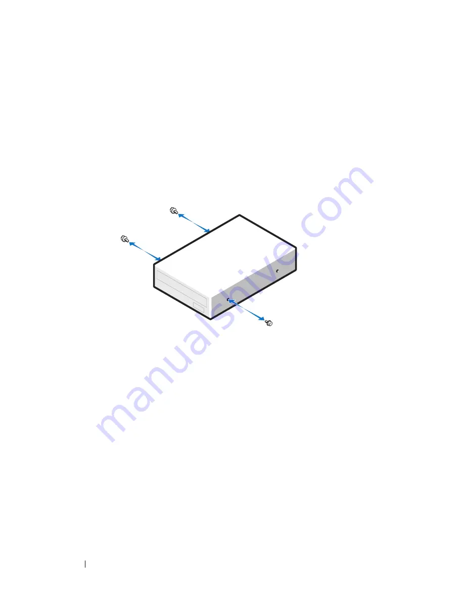
If you are installing a new drive, remove the drive-panel insert (see 
"Removing a Drive-Panel Insert" on page 218) and remove the shoulder 
screws from the inside of the drive-panel insert and attach the screws to 
the new drive.

6

Gently slide the drive into place until the drive securely clicks into 
position.

7

Connect the power cable to the drive, and connect the CD/DVD-drive 
cable to the drive and to the system board.

Содержание Precision NT499

Страница 1: ...w w w d e l l c o m s u p p o r t d e l l c o m Dell Precision Workstation T3400 User s Guide Model DCTA ...

Страница 2: ... of Dell Inc is strictly forbidden Trademarks used in this text Dell the DELL logo Dell Precision and Dell OpenManage are trademarks of Dell Inc Intel and Pentium are registered trademarks of Intel Corporation Microsoft Windows and Vista are either trademarks or registered trademarks of Microsoft Corporation in the United States and or other countries Computrace and Absolute are registered tradema...

Страница 3: ...iew Desktop Orientation 25 Back View Desktop Orientation 28 Back Panel Connectors 29 Specifications 31 3 Advanced Features 39 LegacySelect Technology Control 39 Manageability 39 Dell OpenManage IT Assistant 39 Dell OpenManage Client Instrumentation 40 Power Management 40 4 About RAID Configurations 43 Using RAID with Hard Drive Passwords 43 ...

Страница 4: ...onfiguration 56 Migrating to a RAID Level 1 Configuration 57 Migrating to a RAID Level 5 Configuration 57 Migrating to a RAID Level 10 Configuration 58 Creating a Spare Hard Drive 59 Rebuilding a Degraded RAID Level 1 Configuration 60 5 Setting Up Your Computer 61 Changing Between Tower and Desktop Orientations 61 Switching From Tower to Desktop Orientation 61 Switching From Desktop to Tower Orien...

Страница 5: ...t Readers 72 Passwords 72 About Passwords 73 Using a Primary System Password 74 Using an Administrator Password 74 Using a Hard Drive Password 75 Trusted Platform Module TPM 76 Turning On and Activating TPM 76 Security Management Software 77 Computer Tracking Software 77 If Your Computer Is Lost or Stolen 78 7 Cleaning Your Computer 79 Computer Keyboard and Monitor 79 Mouse Non Optical 79 Floppy D...

Страница 6: ...ng Boot Sequence for Future Boots 94 9 Clearing Passwords and CMOS Settings 95 Clearing Passwords 95 Clearing CMOS Settings 96 Flashing the BIOS 97 10 Troubleshooting Tools 99 Power Lights 99 Diagnostic Lights 100 Diagnostic Light Codes During POST 100 Beep Codes 104 System Messages 105 Hardware Troubleshooter 107 Dell Diagnostics 107 When to Use the Dell Diagnostics 108 ...

Страница 7: ... Internet Problems 115 Error Messages 117 IEEE 1394 Device Problems 118 Keyboard Problems 118 Lockups and Software Problems 119 The computer does not start up 119 The computer stops responding 119 A program stops responding 119 A program crashes repeatedly 119 A program is designed for an earlier Windows operating system 120 A solid blue screen appears 120 Other software problems 120 Memory Proble...

Страница 8: ...ly part of the screen is readable 129 12 Reinstalling Software 131 Drivers 131 What Is a Driver 131 Identifying Drivers 131 Reinstalling Drivers and Utilities 132 Restoring Your Operating System 136 Using Microsoft Windows System Restore 136 Using Dell PC Restore and Dell Factory Image Restore 138 Using the Operating System Media 141 13 Adding and Replacing Parts 143 Before You Begin 143 Recommend...

Страница 9: ...mory 157 Memory Overview 157 Removing a Memory Module 160 Installing a Memory Module 160 Cards 162 PCI Cards 163 PCI Express Cards 175 Drives 185 Tower Computer Drive Configurations 185 Desktop Computer Drive Configurations 187 About Metal Shields Present in Some Drive Configurations 188 General Installation Guidelines 189 Hard Drive 191 Removing a Hard Drive Tower or Desktop Computer 191 Installi...

Страница 10: ...sktop Computer 215 Replacing the Drive Panel Desktop Computer 216 Removing a Drive Panel Insert 218 Installing a Drive Panel Insert 218 Floppy Drive or Media Card Reader 219 Removing a Floppy Drive or Media Card Reader Tower Computer 220 Installing a Floppy Drive or Media Card Reader Tower Computer 222 Removing a Floppy Drive or a Media Card Reader Desktop Computer 226 Installing a Floppy Drive or...

Страница 11: ...252 Replacing the I O Panel 255 Power Supply 256 Removing the Power Supply 256 Replacing the Power Supply 257 System Board 258 Removing the System Board 258 Replacing the System Board 260 Replacing the Front Panel 261 Replacing the Computer Cover 262 14 Getting Help 263 Obtaining Assistance 263 Technical Support and Customer Service 264 DellConnect 264 Online Services 264 AutoTech Service 265 Auto...

Страница 12: ...Your Order 265 Product Information 266 Returning Items for Warranty Repair or Credit 266 Before You Call 267 Contacting Dell 269 15 Appendix 271 FCC Notice U S Only 271 FCC Class B 271 Macrovision Product Notice 272 Glossary 273 ...

Страница 13: ...Contents 13 ...

Страница 14: ...14 Contents ...

Страница 15: ...Disc NOTE The Drivers and Utilities disc may be optional and may not ship with your computer Documentation and drivers are already installed on your computer You can use the Drivers and Utilities disc to reinstall drivers see Reinstalling Drivers and Utilities on page 132 or to run the Dell Diagnostics see Dell Diagnostics on page 107 Readme files may be included on your disc to provide last minut...

Страница 16: ...nditions U S only Safety instructions Regulatory information Ergonomics information End User License Agreement Dell Product Information Guide How to remove and replace parts Specifications How to configure system settings How to troubleshoot and solve problems Dell Precision User s Guide Microsoft Windows XP and Windows Vista Help and Support Center 1 Click Start Help and Support Dell User and Sys...

Страница 17: ...uter Use the Service Tag to identify your computer when you use support dell com or contact support Enter the Express Service Code to direct your call when contacting support NOTE As an increased security measure the newly designed Microsoft Windows license label incorporates a missing portion or hole to discourage removal of the label What Are You Looking For Find It Here ...

Страница 18: ...rt dell com NOTE Select your region or business segment to view the appropriate support site Desktop System Software DSS If you reinstall the operating system for your computer you should also reinstall the DSS utility DSS automatically detects your computer and operating system and installs the updates appropriate for your configuration providing critical updates for your operating system and sup...

Страница 19: ...ating System Media The operating system is already installed on your computer To reinstall your operating system use the Operating System reinstallation media that came with your computer see Restoring Your Operating System on page 136 After you reinstall your operating system use the optional Drivers and Utilities disc to reinstall drivers for the devices that came with your computer Your operati...

Страница 20: ... users of Dell Precision products and the Linux operating system Additional information regarding Linux and my Dell Precision computer Dell Supported Linux Sites linux dell com lists us dell com mailman listinfo linux precision What Are You Looking For Find It Here ...

Страница 21: ...5 25 inch drive bay Supports an optical drive 2 lower 5 25 inch drive bay Supports an optical drive or an additional hard drive SATA only 3 upper 3 5 inch drive bay Supports a floppy drive a Media Card Reader or an additional hard drive SATA or SAS 1 9 10 11 12 13 14 4 5 6 7 8 3 2 ...

Страница 22: ...es see System Setup on page 81 for more information on booting to a USB device NOTE It is recommended that you use the back USB connectors for devices that typically remain connected such as printers and keyboards 8 Dell badge rotatable Use the plastic handle on the back of the Dell badge to rotate the badge for tower to desktop or desktop to tower conversion 9 power button Press to turn on the co...

Страница 23: ...n about sleep states and exiting from a power saving state see Power Management on page 40 For a description of diagnostic light codes for troubleshooting problems with your computer see Diagnostic Lights on page 100 11 microphone connector Use the microphone connector to attach a personal computer microphone for voice or musical input into a sound or telephony program 12 headphone connector Use t...

Страница 24: ...wer cable 2 voltage selection switch See the safety instructions in the Product Information Guide for more information NOTE The voltage selection switch is available on the 375 W PSU only 3 back panel connectors Plug serial USB and other devices into the appropriate connector 1 2 3 4 ...

Страница 25: ...that require more physical space and power such as PCI Express graphics cards may restrict the use of other cards 1 upper 5 25 inch drive bay Supports an optical drive 2 lower 5 25 inch drive bay Supports an optical drive or an additional hard drive SATA only 3 3 5 inch drive bay Supports a floppy drive or a Media Card Reader 4 hard drive activity light The hard drive activity light is on when the...

Страница 26: ...USB device NOTE It is recommended that you use the back USB connectors for devices that typically remain connected such as printers and keyboards 7 power button Press to turn on the computer NOTICE To avoid losing data do not use the power button to turn off the computer Instead perform an operating system shutdown NOTICE If your operating system has ACPI enabled when you press the power button th...

Страница 27: ...about sleep states and exiting from a power saving state see Power Management on page 40 For a description of diagnostic light codes for troubleshooting problems with your computer see Diagnostic Lights on page 100 9 diagnostic lights 4 Use the diagnostic lights to help you troubleshoot a problem with your computer see Diagnostic Lights on page 100 10 microphone connector Use the microphone connec...

Страница 28: ...cards that require more physical space and power such as PCI Express graphics cards may restrict the use of other cards 2 power connector Insert the power cable 3 voltage selection switch See the safety instructions in the Product Information Guide for more information NOTE The voltage selection switch is available on the 375 W PSU only 4 back panel connectors Plug serial USB and other devices int...

Страница 29: ... connector NOTE The integrated parallel connector is automatically disabled if the computer detects an installed card containing a parallel connector configured to the same address For more information see System Setup Options on page 82 3 link integrity light Green A good connection exists between a 10 Mbps network and the computer Orange A good connection exists between a 100 Mbps network and th...

Страница 30: ...e network speed to 10 Mbps to ensure reliable operation 5 network activity light The network activity light is on flashing when the computer is transmitting or receiving network data A high volume of network traffic may make this light appear to be in a steady on state 6 line out connector Use the green line out connector to attach headphones and most speakers with integrated amplifiers On compute...

Страница 31: ...erial connector Connect a serial device such as a handheld device to the serial port The default designations are COM1 for serial connector 1 and COM2 for the optional serial connector 2 For more information see System Setup Options on page 82 11 keyboard connector If you have a PS 2 keyboard plug it into the purple keyboard connector If you have a USB keyboard plug it into a USB connector Process...

Страница 32: ...not detecting a physical connection to the network SAS controller add in SAS 6 iR card System clock 800 MHz 1066 MHz or 1333 MHz data rate depending on your processor Controller Hard drive integrated serial ATA 4 with RAID 0 RAID 1 RAID 5 RAID 10 0 1 and command queuing Drives Available devices serial ATA drive SAS drive floppy drive CD drive DVD drive Media Card Reader and USB memory devices Exte...

Страница 33: ...bit operating systems BIOS address F0000h Connectors External connectors Serial one 9 pin connector 16550C compatible Parallel one 25 hole connector bidirectional IEEE 1394a b one front panel 6 pin serial connector with optional card Video DVI connector on graphics card VGA connector on graphics card Network adapter RJ45 connector PS 2 keyboard and mouse two 6 pin mini DIN USB two front panel and ...

Страница 34: ... 4 pin connector chassis intrusion switch 3 pin connector Video Type PCI Express x16 NOTICE Installing graphics cards that exceed the specified wattage for your power supply may result in your computer not functioning properly See the documentation for your graphics card for power requirements Supported Configurations 375 W PSU 75 W PCI Express x16 single or dual NOTE 150 W PCI Express x16 graphic...

Страница 35: ...ower problem see Power Problems on page 123 Hard drive access light green Link integrity light on integrated network adapter and on front panel on back panel integrated network adapter green light for 10 Mb operation orange light for 100 Mb operation yellow light for a 1000 Mb 1 Gb operation on front panel displays solid green when a network connection is present Activity light on integrated netwo...

Страница 36: ...265 V at 50 60 Hz Backup battery 3 V CR2032 lithium coin cell Physical Height 44 8 cm 17 6 inches Width 17 1 cm 6 8 inches Depth 46 7 cm 18 4 inches Weight 17 7 kg 39 lb Supported monitor weight in desktop orientation 45 4 kg 100 lb Environmental Temperature Operating 10 to 35 C 50 to 95 F Storage 40 to 65 C 40 to 149 F Relative humidity 20 to 80 noncondensing Maximum vibration Operating 0 25 G at...

Страница 37: ...lf sine pulse with a change in velocity of 50 8 cm sec 20 inches sec Storage 27 G faired square wave with a velocity change of 508 cm sec 200 inches sec Altitude Operating 15 2 to 3048 m 50 to 10 000 ft Storage 15 2 to 10 668 m 50 to 35 000 ft Environmental ...

Страница 38: ...38 About Your Computer ...

Страница 39: ...ive and a PS 2 mouse Connectors and media devices that are deactivated make resources available You must restart the computer to effect the changes Manageability Dell OpenManage IT Assistant IT Assistant configures manages and monitors computers and other devices on a corporate network IT Assistant manages assets configurations events alerts and security for computers equipped with industry standa...

Страница 40: ...anagement Your computer can be set to use less power when you are not working You control the power usage through the operating system installed on your computer and certain option settings in System Setup Such periods of reduced power are called sleep states Standby Windows XP Power is reduced or turned off for most components including the cooling fans however system memory remains active Sleep ...

Страница 41: ...ate Standby and or Sleep feature s and have the appropriate drivers loaded to enter either of these sleep states For more information see the manufacturer s documentation for each component The following table lists the sleep states and the corresponding methods you can use to wake the computer NOTE For more information on power management see your operating system documentation Sleep Mode Wake Up...

Страница 42: ...42 Advanced Features ...

Страница 43: ...ame size to ensure that the larger drive does not contain unallocated and therefore unusable space The Intel RAID controller on your computer can only create a RAID level 0 configuration using two or three physical drives If a third or fourth drive is present then the drive s can be made part of a RAID level 0 configuration using the Intel RAID configuration program or the drive s can be used as a...

Страница 44: ...ntage of a RAID level 0 configuration is that it utilizes the full storage capacities of the drives For example two 120 GB hard drives combine to provide 240 GB of hard drive space on which to store data NOTE In a RAID level 0 configuration the size of the configuration is equal to the size of the smallest drive multiplied by the number of drives in the configuration RAID Level 1 RAID level 1 uses...

Страница 45: ...the data is duplicated on at least three other drives Unlike a RAID level 1 configuration which writes to one other volume that acts as a data mirror a RAID level 5 configuration writes data to each drive in increments placing data from each segment across multiple drives A RAID level 5 configuration has higher data access rates but requires more storage space than a RAID level 0 or RAID level 1 c...

Страница 46: ...Unlike a RAID level 1 configuration which writes to one other volume that acts as a data mirror a RAID level 10 configuration writes data to each drive in increments which places data from each segment across multiple drives A RAID level 10 configuration has higher data access rates but requires more storage space than a RAID level 0 or RAID level 1 configuration hard drive 1 segment 1 segment 2 s...

Страница 47: ...up a RAID configuration For instructions on how to install a hard drive see Hard Drive on page 191 You can use one of two methods to configure RAID hard drive volumes One method uses the Intel RAID Option ROM utility and is performed before you install the operating system onto the hard drive The second method uses the Intel Matrix Storage Manager or Intel Matrix Storage Console and this method is...

Страница 48: ...for RAID Using the Intel RAID Option ROM Utility NOTE Although any size of drives may be used to create a RAID configuration when using the Intel RAID Option ROM utility ideally the drives should be of equal size In a RAID level 0 configuration the size of the configuration will be the size of the smallest drive multiplied by the number two of drives in the configuration In a RAID level 1 configur...

Страница 49: ...size 7 Press the up and down arrow keys to change the strip size and press Enter 8 Select the desired capacity for the volume and press Enter The default value is the maximum available size 9 Press Enter to create the volume 10 Press y to confirm that you want to create the RAID volume 11 Confirm that the correct volume configuration is displayed on the main Intel RAID Option ROM utility screen 12...

Страница 50: ...rating System on page 136 Creating a RAID Level 5 Configuration 1 Set your computer to RAID enabled mode see Setting Your Computer to RAID Enabled Mode on page 48 2 Press Ctrl i when you are prompted to enter the Intel RAID Option ROM utility 3 Use the up and down arrow keys to highlight Create RAID Volume and press Enter 4 Enter a RAID volume name or accept the default and press Enter 5 Use the u...

Страница 51: ... the four drives you want to use to make up your volume and then press Enter 7 Select the desired capacity for the volume and press Enter The default value is the maximum available size 8 Press Enter to create the volume 9 Press y to confirm that you want to create the RAID volume 10 Confirm that the correct volume configuration is displayed on the main Intel RAID Option ROM utility screen 11 Use ...

Страница 52: ...xisting single drive computer and the operating system is on the single drive and you want to configure the two new drives into a RAID volume You already have a two hard drive computer configured into a volume but you still have some space left on the volume that you want to designate as a second RAID volume Creating a RAID Level 0 Configuration NOTE When you perform this operation all data on the...

Страница 53: ...rage Manager Intel Matrix Storage Console to launch the Intel Storage Utility NOTE If you do not see an Actions menu option you have not yet set your computer to RAID enabled mode 3 On the Actions menu select Create RAID Volume to launch the Create RAID Volume Wizard 4 Click Next at the first screen 5 Confirm the volume name select RAID 1 as the RAID level and then click Next to continue 6 On the ...

Страница 54: ... screen click the first hard drive you want to use to create your RAID level 5 volume and then click the right arrow Click two or three additional drives until either three or four drives appear in the Selected window and then click Next 7 In the Specify Volume Size window select the Volume Size desired and click Next 8 Click Finish to create the volume or click Back to make changes 9 Follow Micro...

Страница 55: ...low Microsoft Windows procedures for creating a partition on the new RAID volume Deleting a RAID Volume NOTE While this procedure deletes the RAID 1 volume it also splits the RAID 1 volume into two non RAID hard drives with a partition and leaves any existing data files intact Deleting a RAID 0 volume however destroys all data on the volume 1 Click the Start button and point to Programs Intel R Ma...

Страница 56: ...verage file you want to store on the RAID volume If you do not know the average file size choose 128 KB as your strip size 7 Select the appropriate strip size from the drop down box and then click Next NOTE Select the hard drive that you want to use as your source hard drive it should be the hard drive containing the data or operating system files that you want to keep on the RAID volume 8 On the ...

Страница 57: ...ould be the hard drive containing the data or operating system files that you want to keep on the RAID volume 7 On the Select Source Hard Drive screen double click the hard drive from which you want to migrate and click Next 8 On the Select Member Hard Drive screen double click the hard drive to select the member drive that you want to act as the mirror in the configuration and click Next 9 On the...

Страница 58: ...e drives to select the member drives that you want to use in the configuration and click Next 9 On the Specify Volume Size screen select the volume size you want and click Next NOTE In step 10 all data contained on the member drive will be removed 10 Click Finish to start migrating or click Back to make changes You can use your computer normally during migration process Migrating to a RAID Level 1...

Страница 59: ... or click Back to make changes You can use your computer normally during migration process Creating a Spare Hard Drive A spare hard drive may be created with a RAID level 1 configuration The spare hard drive will not be recognized by the operating system but you will be able to see the spare drive from within Disk Manager or the Intel RAID Option ROM utility When a member of the RAID level 1 confi...

Страница 60: ...build the computer s redundancy mirror to a new hard drive 1 Click the Start button and point to Programs Intel R Matrix Storage Manager Intel Matrix Storage Console to launch the Intel Storage Utility 2 Right click the available hard drive to which you want to rebuild the RAID level 1 volume and click Rebuild to this Disk 3 You can use your computer while the computer is rebuilding the RAID level...

Страница 61: ...emoving the Computer Cover on page 145 3 Remove the front panel see Removing the Front Panel on page 154 4 Remove the drive panel and prepare the drive panel by adding or removing inserts as needed see Drive Panel on page 212 Switching From Tower to Desktop Orientation 1 Remove all installed floppy drives or media card readers by following the steps in Removing a Floppy Drive or Media Card Reader ...

Страница 62: ...ve Desktop Computer on page 236 and reinstall the drives by following the steps in Installing an Optical Drive Tower Computer on page 233 Installing Your Computer in an Enclosure Installing your computer in an enclosure can restrict airflow can cause your computer to overheat and may impact your computer s performance Follow the guidelines below when installing your computer in an enclosure NOTICE...

Страница 63: ...or proper ventilation If your computer is installed in a corner on or under a desk leave 5 1 cm 2 in minimum clearance from the back of the computer to the wall to permit the airflow required for proper ventilation If your enclosure has doors ensure that they allow at least thirty percent airflow through the enclosure front and back ...

Страница 64: ...4 Setting Up Your Computer Do not install your computer in an enclosure that does not allow airflow Restricting the airflow can cause your computer to overheat and may impact your computer s performance ...

Страница 65: ...must use the Network Connections utility in the Control Panel to perform additional configuration steps such as setting up an advanced connection and designating the host computer and the guest computer For instructions on setting up a direct cable connection between two computers see Microsoft Knowledge Base Article 305621 titled How to Set Up a Direct Cable Connection Between Two Computers in Wi...

Страница 66: ...o your old computer and then go to the source computer Do not click Next COPY DATA FROM THE SOURCE COMPUTER 1 Insert the Windows XP Operating System installation media into the source computer The Welcome to Microsoft Windows XP screen appears 2 Click Perform additional tasks 3 Under What do you want to do click Transfer files and settings The Files and Settings Transfer Wizard window appears 4 Cl...

Страница 67: ...s the old computer and designates the destination computer to which the data is going to be transferred as the new computer CREATE A WIZARD DISK 1 On the destination computer click Start All Programs Accessories System Tools Files and Settings Transfer Wizard 2 Under Which computer is this click New computer then click Next 3 Under Do you have a Windows XP CD click I want to create a Wizard Disk i...

Страница 68: ...ds the collected files and settings and applies them to the destination computer When the transfer is complete the Finished screen appears 4 Click Finished and then restart the computer Microsoft Windows Vista 1 Click the Windows Vista Start button and then click Transfer files and settings Start Windows Easy Transfer 2 In the User Account Control dialog box click Continue 3 Click Start a new tran...

Страница 69: ...ction See the surge protector documentation for modem connection instructions NOTICE Not all surge protectors offer network adapter protection Disconnect the network cable from the network wall jack during electrical storms Line Conditioners NOTICE Line conditioners do not protect against power interruptions Line conditioners are designed to maintain AC voltage at a fairly constant level Uninterru...

Страница 70: ...70 Setting Up Your Computer ...

Страница 71: ...changes to Detected and an alert message displays during the boot routine at the next computer start up On Silent default The Chassis Intrusion dectection feature is enabled If the computer cover is opened the setting changes to Detected however no alert message appears during the boot routine at the next computer start up NOTE For information on changing System Setup options see System Setup on p...

Страница 72: ...ral device for your computer When you slide your finger over the reader it uses your unique fingerprint to authenticate your user identity and help keep your Dell computer secure Passwords Passwords prevent unauthorized access to your computer When using passwords observe the following guidelines Choose a password that you can remember but not one that is easy to guess For example do not use the n...

Страница 73: ...ryption features NOTE Passwords are disabled when you receive your computer The following table identifies types and features of passwords available on your computer If you forget a password contact Dell see Contacting Dell on page 269 For your protection Dell support will require verification of your identity to ensure that only an authorized person can use the computer Type of Password Features ...

Страница 74: ...vice technicians access to computers for repair or reconfiguration The administrators or technicians can assign identical administrator passwords to groups of computers allowing you to assign a unique primary password To set or change administrator passwords access User Accounts from the Control Panel When you set an administrator password the Configure Setup option becomes available in System Set...

Страница 75: ...n invalid password is entered three times consecutively the computer tries to start from another bootable device if the Boot First Device option in System Setup is set to allow start up from another device If the Boot First Device option is not set to allow the computer to start from another device the computer returns to the operating state it was in when you turned it on If a valid password is n...

Страница 76: ...sist in the recovery of encrypted data Turning On and Activating TPM 1 Enter System Setup see Entering System Setup on page 81 2 Use the up and down arrow keys to highligh Security then press Enter 3 Use the up and down arrow keys to highlight TPM Security then press Enter 4 Under TPM Security use the left and right arrow keys to select On and then press Enter The TPM Activation menu appears NOTE ...

Страница 77: ...ation using a fingerprint reader smart card or password Encryption Private information management For information about how to use the software and the different security features click Start All Programs Security by Wave Systems Getting Started with EMBASSY Trust Suite Computer Tracking Software Computer tracking software may enable you to locate your computer if it is lost or stolen The software...

Страница 78: ...company notify the security office of the company Contact Dell customer service to report the missing computer Provide the computer Service Tag the case number and the name address and phone number of the law enforcement agency to which you reported the missing computer If possible give the name of the investigating officer The Dell customer service representative will log your report under the co...

Страница 79: ... Do not wipe the display screen with a soap or alcohol solution Doing so may damage the antiglare coating To clean your monitor screen lightly dampen a soft clean cloth with water If possible use a special screen cleaning tissue or solution suitable for the monitor s antistatic coating Wipe the keyboard computer and plastic part of the monitor with a soft cleaning cloth moistened with water Do not...

Страница 80: ...Ds and DVDs NOTICE Always use compressed air to clean the lens in the CD DVD drive and follow the instructions that come with the compressed air Never touch the lens in the drive 1 Hold the disc by its outer edge You can also touch the inside edge of the center hole NOTICE To prevent damaging the surface do not wipe in a circular motion around the disc 2 With a soft lint free cloth gently wipe the...

Страница 81: ...our computer to work incorrectly Entering System Setup 1 Turn on or restart your computer 2 When the DELL logo appears press F2 immediately NOTE Keyboard failure may result when a key on the keyboard is held down for extended periods of time To avoid possible keyboard failure press and release F2 in even intervals until the System Setup screen appears If you wait too long and the operating system ...

Страница 82: ...indow and contains information about each option listed in the Options List In this field you can view information about your computer and make changes to your current settings Press the left and right arrow keys to highlight an option Press Enter to make that selection active and return to the Options List NOTE Not all settings listed in the Options Field are changeable Key Functions Appears belo...

Страница 83: ... Internal default Enables and disables the floppy drive s attached to the computer and sets read permissions for the drive s Off All floppy drives are disabled USB USB floppy drives are enabled Internal The integrated floppy drive is enabled Read Only The integrated floppy drive is enabled with read only access NOTE Operating systems with USB support will recognize USB floppy drives regardless of ...

Страница 84: ...empts to boot from the next device listed in the boot sequence Integrated Audio Auto default Enables or disables the integrated audio controller Off Integrated audio is disabled Auto Use the add in Audio controller On Integrated audio is enabled USB Controller On default Enables or disables the internal USB controller Off The USB controller is disabled On The USB controller is enabled No Boot The ...

Страница 85: ...pability Port protocol LPT Port Address 378h default Specifies the base I O address for the integrated parallel port 378h 278h 3BCh Serial Port 1 Auto default Disables or selects the address for the integrated serial port and determines how the serial port operates Off The serial port is disabled Auto The BIOS selects between COM1 and COM3 if both resources are in use the port is disabled COM1 The...

Страница 86: ...bled SpeedStep Off default Specifies whether Enhanced SpeedStep Technology is enabled for all supported processor s in the system Off Enhanced SpeedStep Technology is disabled On Enhanced SpeedStep Technology is enabled Virtualization Off default Specifies whether a Virtual Machine Monitor VMM can utilize the additional hardware capabilities provided by Intel Virtualization Technology Off Virtuali...

Страница 87: ...rd Not Set default Used to prohibit an unauthorized user from changing any configuration settings in System Setup System Password Not Set default Used to prohibit an unauthorized user from booting to the operating system Drives 0 through 5 Password Not Set default Used to prohibit an unauthorized user from accessing the hard drive Password Changes Unlocked default Controls the interaction between ...

Страница 88: ...sabled On The TPM security device is enabled NOTE When TPM Security is set to On the operating system recognizes TPM but TPM is not activated enabled TPM Activation Deactivate default Enables or disables the TPM security device Activate Enables and activates TPM security Deactivate Deactivates and disables TPM security Clear Clears TPM security ownership data NOTE The TPM Activation menu appears o...

Страница 89: ... of information from and to your computer and the Absolute Software Monitoring Server NOTE Selecting the Activate or Disable option permanently Activates or Disables the feature and no further changes to this setting are allowed Power Management AC Recovery Off default Specifies how the computer will behave when AC power is restored after an AC power loss Off The computer stays off after AC power ...

Страница 90: ...rnate mode or turned off Only an add in NIC can be used to remotely wake the system Remote Wake Up Off default Specifies whether the computer can be turned on when a NIC receives a wake up signal Off The NIC cannot wake up the system On The NIC can wake up the system On w Boot to NIC The NIC can wake up the system and the system will boot from the network NOTE The system can be powered on remotely...

Страница 91: ...talled default settings Cancel Do not restore factory installed default settings Continue Restore factory installed default settings Event Log Displays the system event log Mark all entries Mark all event log entries as read R Clear log Clear all event log entries NOTE Once an event log entry is marked as read R that entry cannot be marked as unread U POST Behavior Fastboot On default Enables or d...

Страница 92: ...ce Onboard SATA Hard Drive The computer attempts to boot from the primary hard drive If no operating system is on the drive the computer attempts to boot from the next bootable device in the boot sequence Onboard or USB CD ROM Drive The computer attempts to boot from the CD drive If no CD is in the drive or if the CD has no operating system the computer attempts to boot from the next bootable devi...

Страница 93: ...mory key or hard drive NOTE If you are booting to a USB floppy drive you must first set the floppy drive to OFF in System Setup see System Setup on page 81 1 If you are booting to a USB device connect the USB device to a USB connector see Back View Tower Orientation on page 24 or Back View Desktop Orientation on page 28 2 Turn on or restart your computer 3 When the DELL logo appears press F12 imme...

Страница 94: ...p see Entering System Setup on page 81 2 Use the arrow keys to highlight the Boot Sequence menu option and press Enter to access the menu NOTE Write down your current boot sequence in case you want to restore it later 3 Press the up and down arrow keys to move through the list of devices 4 Press the spacebar to enable or disable a device 5 Press plus or minus to move a selected device up or down t...

Страница 95: ...located in the Product Information Guide 1 Follow the procedures in Before You Begin on page 143 2 Remove the computer cover see Removing the Computer Cover on page 145 3 Locate the 4 pin password connector RTCRST_PSWD on the system board 4 Remove the 2 pin jumper plug from pins 3 and 4 and set the jumper plug aside 5 Replace the computer cover see Replacing the Computer Cover on page 262 ...

Страница 96: ...he password connector RTCRST_PSWD on the system board NOTE The password jumper plug must be reinstalled on the password jumper pins in order to enable the password feature NOTICE To connect a network cable first plug the cable into the network wall jack and then plug it into the computer 12 Connect your computer and devices to electrical outlets and then turn them on NOTE In System Setup see Syste...

Страница 97: ... may require flashing when an update is available or when replacing the system board 1 Turn on the computer 2 Locate the BIOS update file for your computer at the Dell Support website at support dell com 3 Click Download Now to download the file 4 If the Export Compliance Disclaimer window appears click Yes I Accept this Agreement The File Download window appears 5 Click Save this program to disk ...

Страница 98: ...98 Clearing Passwords and CMOS Settings ...

Страница 99: ...ot receiving power Reseat the power cable into both the power connector on the back of the computer and the electrical outlet If the computer is plugged into a power strip ensure that the power strip is plugged into an electrical outlet and that the power strip is turned on Bypass power protection devices power strips and power extension cables to verify that the computer turns on properly Ensure ...

Страница 100: ...n any of the procedures in this section follow the safety instructions in the Product Information Guide To help troubleshoot a problem your computer has four lights labeled 1 2 3 and 4 on the front panel see Front View Tower Orientation on page 21 or Front View Desktop Orientation on page 25 When the computer starts normally the lights flash and then turn off If the computer malfunctions use the s...

Страница 101: ...page 160 and restart the computer If the computer starts normally continue to install additional memory modules one at a time until you have identified a faulty module or reinstalled all modules without error If available install working memory of the same type into your computer see Memory on page 157 If the problem persists contact Dell see Contacting Dell on page 269 A possible graphics card fa...

Страница 102: ...ll working memory of the same type into your computer see Memory on page 157 If the problem persists contact Dell see Contacting Dell on page 269 System board failure has occurred Contact Dell see Contacting Dell on page 269 Memory modules are detected but a memory configuration or compatibility error exists Ensure that no special requirements for memory module connector placement exist see Memory...

Страница 103: ... persists contact Dell see Contacting Dell on page 269 Another failure has occurred Ensure that all hard drive and CD DVD drive cables are properly connected to the system board see System Board Components on page 148 If there is an error message on the screen identifying a problem with a device such as the floppy drive or hard drive check the device to make sure it is functioning properly If the ...

Страница 104: ...s Description Suggested Remedy 1 BIOS checksum failure Possible motherboard failure Contact Dell see Contacting Dell on page 269 2 No memory modules are detected If two or more memory modules are installed remove the modules see Removing a Memory Module on page 160 then reinstall one module see Installing a Memory Module on page 160 and restart the computer If the computer starts normally continue...

Страница 105: ...lure Possible battery failure or motherboard failure Replace the battery see Replacing the Battery on page 251 If the problem persists contact Dell see Contacting Dell on page 269 6 Video BIOS Test Failure Contact Dell see Contacting Dell on page 269 ALERT PREVIOUS ATTEMPTS AT BOOTING THIS SYSTEM HAVE FAILED AT CHECKPOINT NNNN FOR HELP IN RESOLVING THIS PROBLEM PLEASE NOTE THIS CHECKPOINT AND CONT...

Страница 106: ...ble loose see Keyboard Problems on page 118 NO BOOT DEVICE AVAILABLE The system cannot detect a bootable device or partition If the floppy drive is your boot device ensure that the cables are connected and that a bootable floppy disk is in the drive If the hard drive is your boot device ensure that the cables are connected and that the drive is installed properly and partitioned as a boot device E...

Страница 107: ...ista start button and click Help and Support 2 Type hardware troubleshooter in the search field and press Enter to start the search 3 In the search results select the option that best describes the problem and follow the remaining troubleshooting steps Dell Diagnostics CAUTION Before you begin any of the procedures in this section follow the safety instructions in the Product Information Guide NOT...

Страница 108: ...rom Your Hard Drive The Dell Diagnostics is located on a separate diagnostic utility partition on your hard drive NOTE If your computer cannot display a screen image see Contacting Dell on page 269 1 Turn on or restart your computer 2 When the DELL logo appears press F12 immediately NOTE Keyboard failure may result when a key is held down for extended periods of time To avoid possible keyboard fai...

Страница 109: ...st window to return to the Dell Diagnostics Main Menu 6 Close the Main Menu window to exit the Dell Diagnostics and restart the computer Starting the Dell Diagnostics From the Drivers and Utilities Disc 1 Turn on your computer 2 Press the eject button on the front of the optical drive to open the drive tray 3 Place the Drivers and Utilities disc in the center of the drive tray then press the eject...

Страница 110: ...uctions on the screen 10 After all tests have completed close the test window to return to the Dell Diagnostics Main Menu 11 Remove the Drivers and Utilities disc then close the Main Menu window to exit the Dell Diagnostics and restart the computer Dell Diagnostics Main Menu The following tests can be run from the Dell Diagnostics Main Menu Option Function Express Test Performs a quick test of sys...

Страница 111: ...Tab Function Results Displays the results of the test and any error conditions encountered Errors Displays error conditions encountered error codes and the problem description Help Describes the test and any requirements for running the test Configuration Custom Test only Displays the hardware configuration for the selected device The Dell Diagnostics obtains configuration information for all devi...

Страница 112: ...112 Troubleshooting Tools ...

Страница 113: ...he Windows Classic view Battery Problems CAUTION There is a danger of a new battery exploding if it is incorrectly installed Replace the battery only with the same or equivalent type recommended by the manufacturer Discard used batteries according to the manufacturer s instructions CAUTION Before you begin any of the procedures in this section follow the safety instructions in the Product Informat...

Страница 114: ... DELL DIAGNOSTICS See Dell Diagnostics on page 107 Optical drive problems NOTE High speed optical drive vibration is normal and may cause noise which does not indicate a defect in the drive or the media NOTE Because of different regions worldwide and different disc formats not all DVD titles work in all DVD drives ADJUST THE WINDOWS VOLUME CONTROL Click the speaker icon in the lower right corner o...

Страница 115: ...strator on the computer click Continue otherwise contact your administrator to continue the desired action 4 Follow the instructions on the screen E Mail Modem and Internet Problems CAUTION Before you begin any of the procedures in this section follow the safety instructions in the Product Information Guide NOTE Connect the modem to an analog telephone jack only The modem does not operate while it...

Страница 116: ...DIAGNOSTIC TOOL Windows XP 1 Click Start All Programs Modem Helper 2 Follow the instructions on the screen to identify and resolve modem problems Modem Helper is not available on certain computers Windows Vista 1 Click Start All Programs Modem Diagnostic Tool 2 Follow the instructions on the screen to identify and resolve modem problems Modem diagnostics are not available on all computers VERIFY T...

Страница 117: ...n reinstall the program Windows XP 1 Click Start Control Panel Add or Remove Programs Programs and Features 2 Select the program you want to remove 3 Click Uninstall 4 See the program documentation for installation instructions Windows Vista 1 Click Start Control Panel Programs Programs and Features 2 Select the program you want to remove 3 Click Uninstall 4 See the program documentation for insta...

Страница 118: ...lick Device Manager If your IEEE 1394 device is listed Windows recognizes the device ENSURE THAT THE IEEE 1394 CARD IS PROPERLY SEATED ENSURE THAT THE IEEE 1394 CABLE IS CONNECTED SECURELY TO THE SYSTEM BOARD CONNECTOR AND THE CONNECTOR ON THE FRONT I O PANEL IF YOU HAVE PROBLEMS WITH A DELL IEEE 1394 DEVICE Contact Dell see Contacting Dell on page 269 IF YOU HAVE PROBLEMS WITH AN IEEE 1394 DEVICE...

Страница 119: ...e Diagnostic Lights on page 100 ENSURE THAT THE POWER CABLE IS FIRMLY CONNECTED TO THE COMPUTER AND TO THE ELECTRICAL OUTLET The computer stops responding NOTICE You may lose data if you are unable to perform an operating system shutdown TURN THE COMPUTER OFF If you are unable to get a response by pressing a key on your keyboard or moving your mouse press and hold the power button for at least 8 t...

Страница 120: ...s version of Windows 2 In the welcome screen click Next 3 Follow the instructions on the screen A solid blue screen appears TURN THE COMPUTER OFF If you are unable to get a response by pressing a key on your keyboard or moving your mouse press and hold the power button for at least 8 to 10 seconds until the computer turns off and then restart your computer Other software problems CHECK THE SOFTWAR...

Страница 121: ...sfully communicating with the memory Run the Dell Diagnostics see Dell Diagnostics on page 107 IF YOU EXPERIENCE OTHER MEMORY PROBLEMS Reseat the memory modules see Memory on page 157 to ensure that your computer is successfully communicating with the memory Ensure that you are following the memory installation guidelines see Installing a Memory Module on page 160 Ensure that the memory you are us...

Страница 122: ...gs as needed REINSTALL THE MOUSE DRIVER See Drivers on page 131 RUN THE HARDWARE TROUBLESHOOTER See Hardware Troubleshooter on page 107 Network Problems CAUTION Before you begin any of the procedures in this section follow the safety instructions in the Product Information Guide CHECK THE NETWORK LIGHT ON THE FRONT OF THE COMPUTER If the link integrity light is off see Controls and Lights on page ...

Страница 123: ...Ensure that any power strips being used are plugged into an electrical outlet and are turned on Ensure that the electrical outlet is working by testing it with another device such as a lamp Ensure that the main power cable and front panel cable are securely connected to the system board see System Board Components on page 148 IF THE POWER LIGHT IS BLINKING AMBER The computer is receiving electrica...

Страница 124: ...urely connected to the printer and the computer TEST THE ELECTRICAL OUTLET Ensure that the electrical outlet is working by testing it with another device such as a lamp VERIFY THAT THE PRINTER IS RECOGNIZED BY WINDOWS Windows XP 1 Click Start Control Panel Printers and Other Hardware View installed printers or fax printers 2 If the printer is listed right click the printer icon 3 Click Properties ...

Страница 125: ...ecurely connected to the scanner and the computer VERIFY THAT THE SCANNER IS RECOGNIZED BY MICROSOFT WINDOWS Windows XP 1 Click Start Control Panel Printers and Other Hardware Scanners and Cameras 2 If your scanner is listed Windows recognizes the scanner Windows Vista 1 Click Start Control Panel Hardware and Sound Scanners and Cameras 2 If the scanner is listed Windows recognizes the scanner REIN...

Страница 126: ...o the computer s front panel headphone connector TEST THE ELECTRICAL OUTLET Ensure that the electrical outlet is working by testing it with another device such as a lamp ELIMINATE POSSIBLE INTERFERENCE Turn off nearby fans fluorescent lights or halogen lamps to check for interference RUN THE SPEAKER DIAGNOSTICS REINSTALL THE SOUND DRIVER See Drivers on page 131 RUN THE HARDWARE TROUBLESHOOTER See ...

Страница 127: ... setup diagram for your computer Remove any video extension cables and connect the monitor directly to the computer Swap the computer and monitor power cables to determine if the monitor s power cable is defective Check the connectors for bent or broken pins it is normal for monitor cable connectors to have missing pins CHECK THE MONITOR POWER LIGHT If the power light is lit or blinking the monito...

Страница 128: ...OUTLET Ensure that the electrical outlet is working by testing it with another device such as a lamp CHECK THE DIAGNOSTIC LIGHTS See Diagnostic Lights on page 100 CHECK THE MONITOR SETTINGS See the monitor documentation for instructions on adjusting the contrast and brightness demagnetizing degaussing the monitor and running the monitor self test MOVE THE SUBWOOFER AWAY FROM THE MONITOR If your sp...

Страница 129: ...he graphics card s is correctly attached to the card CHECK THE MONITOR SETTINGS See the monitor documentation for instructions on adjusting the contrast and brightness demagnetizing degaussing the monitor and running the monitor self test Only part of the screen is readable TURN ON THE COMPUTER AND THE MONITOR AND ADJUST THE MONITOR BRIGHTNESS AND CONTRAST CONTROLS If the monitor works the graphic...

Страница 130: ...130 Troubleshooting ...

Страница 131: ...ICE The Drivers and Utilities disc may contain drivers for operating systems that are not on your computer Ensure that you are installing software appropriate for your operating system Many drivers such as the keyboard driver come with your Microsoft Windows operating system You may need to install drivers if you Upgrade your operating system Reinstall your operating system Connect or install a ne...

Страница 132: ...o continue 3 Scroll down the list of devices and check for an exclamation point a circle with a next to the device name If an exclamation point appears next to the device name you may need to reinstall the driver or install a new driver see Reinstalling Drivers and Utilities on page 132 Reinstalling Drivers and Utilities NOTICE The Dell Support website at support dell com and your Drivers and Util...

Страница 133: ...the new driver was installed then click Properties 4 Click the Driver tab 5 Click Roll Back Driver If Device Driver Rollback does not resolve the problem reinstall the driver from the Drivers and Utilities disc Using the Drivers and Utilities Disc If a problem occurs on your computer after you install or update a driver and Device Driver Rollback does not resolve the problem reinstall the driver f...

Страница 134: ... the screen prompts to complete the installation If no Install button is present automatic installation is not an option For installation instructions either see the appropriate instructions in the following subsections or click Extract follow the extracting instructions and then read the readme file If instructed to navigate to the driver files click the CD DVD directory on the driver information...

Страница 135: ...puter Windows Vista 1 Click the Windows Vista start button then right click Computer 2 Click Properties then click Device Manager NOTE The User Account Control window may appear If you are an administrator on the computer click Continue otherwise contact your administrator to continue 3 Double click the type of device for which you are installing the driver 4 Double click the name of the device fo...

Страница 136: ...operating system However using the Operating System installation media also deletes all data on the hard drive Use the media only if System Restore did not resolve your operating system problem Using Microsoft Windows System Restore The Windows operating systems provide a System Restore option which allows you to return your computer to an earlier operating state without affecting data files Using...

Страница 137: ...he Start Search box type System Restore and press Enter NOTE The User Account Control window may appear If you are an administrator on the computer click Continue otherwise contact your administrator to continue 3 Click Next and follow the instructions on the screen Undoing the Last System Restore NOTICE Before you undo the last system restore save and close all open files and exit any open progra...

Страница 138: ...before using these options Use PC Restore or Dell Factory Image Restore only if System Restore did not resolve your operating system problem NOTE Dell PC Restore by Symantec and Dell Factory Image Restore may not be available in certain countries or on certain computers Use Dell PC Restore Windows XP or Dell Factory Image Restore Windows Vista only as the last method to restore your operating syst...

Страница 139: ...first time the computer was turned on 6 Click Next The System Restore screen appears and the computer restarts 7 After the computer restarts click OK Removing PC Restore NOTICE Removing Dell PC Restore from the hard drive permanently deletes the PC Restore utility from your computer After you have removed Dell PC Restore you will not be able to use it to restore your computer operating system Dell...

Страница 140: ...n Windows Explorer click Properties and verify that the additional disk space is available as indicated by the increased value for Free Space 7 Click Finish to close the PC Restore Removal window and restart the computer Windows Vista Dell Factory Image Restore 1 Turn on the computer When the Dell logo appears press F8 several times to access the Vista Advanced Boot Options window 2 Select Repair ...

Страница 141: ...ting system to the operating state it was in before you installed the new device driver see Using Microsoft Windows System Restore on page 136 NOTICE Before performing the installation back up all data files on your primary hard drive For conventional hard drive configurations the primary hard drive is the first drive detected by the computer To reinstall Windows you need the following items Dell ...

Страница 142: ... if the Install Windows message appears 4 Restart the computer When the DELL logo appears press F12 immediately NOTE If you wait too long and the operating system logo appears continue to wait until you see the Microsoft Windows desktop then shut down your computer and try again NOTE The next steps change the boot sequence for one time only On the next start up the computer boots according to the ...

Страница 143: ...rately installed by performing the removal procedure in reverse order Recommended Tools The procedures in this document may require the following tools Small flat blade screwdriver Small Phillips screwdriver Small plastic scribe Flash BIOS update program Turning Off Your Computer NOTICE To avoid losing data save and close all open files and exit all open programs before you turn off your computer ...

Страница 144: ...ket Hold a component such as a processor by its edges not by its pins NOTICE Only a certified service technician should perform repairs on your computer Damage due to servicing that is not authorized by Dell is not covered by your warranty NOTICE When you disconnect a cable pull on its connector or on its pull tab not on the cable itself Some cables have connectors with locking tabs if you are dis...

Страница 145: ...face to dissipate static electricity which could harm internal components Removing the Computer Cover CAUTION Before you begin any of the procedures in this section follow the safety instructions in the Product Information Guide CAUTION To guard against electrical shock always unplug your computer from the electrical outlet before removing the cover 1 Follow the procedures in Before You Begin on p...

Страница 146: ...dding and Replacing Parts Inside View of Your Computer NOTE If your computer is configured as a desktop computer the drives will appear differently 1 cover release latch 2 computer cover 3 cover hinges 2 3 1 ...

Страница 147: ... system board 3 secondary hard drive bay 4 processor airflow shroud 5 primary hard drive bay 6 card fan 7 processor fan 8 3 5 inch drive bay 9 3 5 inch drive bay 10 5 25 inch drive bay 11 5 25 inch drive bay 12 drive cage 1 3 7 8 11 12 2 4 6 9 10 5 ...

Страница 148: ... 1 power connector 12VPOWER 2 memory module connectors DIMM_1 DIMM_2 DIMM_3 DIMM_4 3 battery socket BATTERY 4 memory fan connector FAN_MEM1 5 front panel connector 6 SATA connectors SATA0 SATA1 8 7 1 9 2 24 3 4 5 20 10 11 16 17 12 13 14 18 23 22 21 6 15 19 ...

Страница 149: ...intrusion header INTRUDER 12 PCI card slot SLOT1 13 PCI Express x16 card slot SLOT2 14 PCI Express x8 card slot wired as x4 SLOT3 15 PCI Express x16 card slot SLOT4 16 PCI card slots SLOT5 SLOT6 17 SAS Card Activity LED AUX_LED 18 floppy drive FLOPPY 19 uDOC connector UDOC1 20 serial connector SERIAL2 21 card cage fan FAN_CARD_ CAGE 22 internal speaker connector INT_SPKR 23 processor fan connector...

Страница 150: ... AWG 6 5 VDC Red 18 AWG 7 COM Black 18 AWG 8 POK Gray 22 AWG 9 5 VFP Purple 18 AWG 10 12 VBDC White 18 AWG 11 12 VBDC White 18 AWG 12 3 3 VDC Orange 18 AWG 13 3 3 VDC SE4 Orange 18 AWG 14 12 VDC Blue 22 AWG 15 COM Black 18 AWG 16 PS_ON Green 22 AWG 17 COM Black 18 AWG 18 COM Black 18 AWG 19 COM Black 18 AWG 20 OPEN 21 5 VDC Red 18 AWG 13 14 15 16 17 18 19 20 21 22 23 24 1 2 3 4 5 6 7 8 9 10 11 12 ...

Страница 151: ... 18 AWG 23 5 VDC Red 18 AWG 24 COM Black 18 AWG Pin Number Signal Name 18 AWG Wire 1 COM Black 2 COM Black 3 12 VADC Yellow 4 12 VADC Yellow Pin Number Signal name 18 AWG Wire 1 3 3 VDC Orange 2 COM Black 3 5 VDC Red 4 COM Black 5 12 VADC Yellow Pin Number Signal name Wire Color Wire Size 3 1 4 2 ...

Страница 152: ...Connector P7 DC Power Connectors P8 P9 P13 and P14 Pin Number Signal name 22 AWG Wire 1 5 VDC Red 2 COM Black 3 COM Black 4 12 VADC Yellow Pin Number Signal name 18 AWG Wire 1 3 3 VDC Orange 2 COM Black 3 5 VDC Red 4 COM Black 5 12 VBDC White ...

Страница 153: ...Connector P10 DC Power Connector P12 Pin Number Signal Name 18 AWG Wire 1 12 VADC Yello 2 COM Black 3 COM Black 4 5 VDC Red Pin Number Signal Name 18 AWG Wire 1 12 VBDC White 2 12 VBDC White 3 12 VBDC White 4 COM Black 5 COM Black 6 COM Black ...

Страница 154: ... in this section follow the safety instructions in the Product Information Guide 1 Follow the procedures in Before You Begin on page 143 2 Remove the computer cover see Removing the Computer Cover on page 145 Pin Number Signal Name 18 AWG Wire 1 12 VCDC Blue White 2 12 VCDC Blue White 3 12 VCDC Blue White 4 COM Black 5 COM Black 6 COM Black ...

Страница 155: ...of the procedures in this section follow the safety instructions in the Product Information Guide 1 Follow the procedures in Before You Begin on page 143 2 Remove the computer cover see Removing the Computer Cover on page 145 3 Disconnect the chassis intrusion switch cable from the system board see System Board Components on page 148 Note the routing of the chassis intrusion switch cable Chassis h...

Страница 156: ...he Product Information Guide 1 Follow the procedures in Before You Begin on page 143 2 Remove the computer cover see Removing the Computer Cover on page 145 3 Gently slide the chassis intrusion switch into its slot then connect the chassis intrusion switch cable to the system board see System Board Components on page 148 4 Replace the computer cover see Replacing the Computer Cover on page 262 NOT...

Страница 157: ...left and right arrow keys to highlight Save Exit and then press Enter to exit System Setup and restart your computer Memory For information on the type of memory supported by your computer see Specifications on page 31 NOTICE Before you install new memory modules download the most recent BIOS for your computer from support dell com Memory Overview Memory modules should be installed in pairs of mat...

Страница 158: ... of matched memory modules installed in connectors DIMM_3 and DIMM_4 If mixed pairs of memory modules are installed the modules function at the speed of the slowest module Install a single memory module in the DIMM_1 connector see System Board Components on page 148 before installing modules in the other connectors When installing memory modules do not mix ECC and non ECC memory A matched pair of ...

Страница 159: ...r require address space in the 4 GB range Any address space reserved for these components cannot be used by computer memory therefore the amount of memory available to the operating system is less than 4 GB NOTE The entire 8 GB memory range is available to 64 bit operating systems The following components require memory address space System ROM APIC s Integrated PCI devices such as network connect...

Страница 160: ...he memory module and lift the module straight up and out of the connector If the memory module is difficult to remove gently ease the module back and forth while pulling up Installing a Memory Module CAUTION Before you begin any of the procedures in this section follow the safety instructions in the Product Information Guide 1 Follow the procedures in Before You Begin on page 143 2 Remove the comp...

Страница 161: ...ign the notch on the bottom of the memory module with the crossbar in the memory module connector 1 memory module connector DIMM_1 2 securing clips 2 3 memory module connector 1 cutouts 2 2 memory module 3 notch 4 crossbar 2 3 1 3 2 1 4 ...

Страница 162: ...twork port or device and then plug it into the computer 7 Connect your computer and devices to electrical outlets and then turn them on 8 Enter System Setup see Entering System Setup on page 81 and verify the value for System Memory The amount of System Memory reflects the newly installed memory NOTE If the amount of memory is incorrect check the installed memory modules to ensure that they are se...

Страница 163: ... begin any of the procedures in this section follow the safety instructions in the Product Information Guide 1 Follow the procedures in Before You Begin on page 143 2 Remove the computer cover see Removing the Computer Cover on page 145 3 Press the release tabs on the card retention door and pivot the door open 1 PCI Express x16 card 2 PCI Express x8 card 3 PCI card 4 PCI card slot 5 PCI Express x...

Страница 164: ...and Replacing Parts 4 Press the release tab on the card retention cover and pivot the cover open NOTE You can remove the card retention cover if desired and set it aside 1 release tabs 2 2 card retention door 2 1 ...

Страница 165: ...nector NOTE If you are removing the card permanently install a filler bracket in the empty card slot opening NOTE Installing filler brackets over empty card slot openings is necessary to maintain FCC certification of the computer The brackets also keep dust and dirt out of your computer 1 release tab 2 card retention cover 3 card retention door 3 1 2 ...

Страница 166: ...166 Adding and Replacing Parts 6 Reinstall the card retention cover if removed 7 Close the card retention cover by snapping it into place to secure the card s ...

Страница 167: ...Adding and Replacing Parts 167 8 Close the card retention door by snapping it into place to secure the card s 1 release tab 2 card retention cover 3 card retention door 3 1 2 ...

Страница 168: ...nto the computer 10 Connect your computer and devices to electrical outlets and then turn them on 11 Uninstall the driver for the removed card See the documentation that came with the card 12 Update System Setup settings as needed If you removed a sound card enter System Setup see Entering System Setup on page 81 select Integrated Audio and then change the setting to On 1 card retention door 2 rel...

Страница 169: ... any of the procedures in this section follow the safety instructions in the Product Information Guide NOTE Dell offers a customer kit for Audigy II and IEEE 1394 PCI cards that includes a front mounted IEEE 1394 connector For more information about connecting the card cable to the I O panel see I O Panel on page 251 1 Follow the procedures in Before You Begin on page 143 2 Remove the computer cov...

Страница 170: ...iguring the card making internal connections or otherwise customizing it for your computer CAUTION Some network adapters automatically start the computer when they are connected to a network To guard against electrical shock be sure to unplug your computer from its electrical outlet before installing any cards NOTE The standard length for a PCI card in the last PCI slot Slot6 is 5 5 in however you...

Страница 171: ...n the connector and press down firmly Ensure that the card is fully seated in the slot the top of the card is flush with the alignment bar and the notch in the top of the card fits around the alignment guide 1 screws 2 2 second hard drive bracket 2 1 ...

Страница 172: ...pment 8 Connect any cables that should be attached to the card See the documentation for the card for information about the card s cable connections 9 Ensure that the tops of all cards and filler brackets are flush with the alignment bar and that the notch in the top of the card or filler bracket fits around the alignment guide 1 PCI card 2 alignment bar 3 alignment guide 4 filler bracket 4 3 2 1 ...

Страница 173: ... retention cover if removed 11 Close the card retention cover by snapping it into place to secure the card s 12 Close the card retention door by snapping it into place to secure the card s 1 release tab 2 card retention cover 3 card retention door 3 1 2 ...

Страница 174: ...ystem Setup settings as needed If you installed a sound card enter System Setup see Entering System Setup on page 81 select Integrated Audio and then change the setting to Off If you installed a network adapter card enter System Setup see Entering System Setup on page 81 select Integrated NIC and then change the setting to Off NOTE Connect your external audio devices or your network cable to the c...

Страница 175: ... section follow the safety instructions in the Product Information Guide 1 Follow the procedures in Before You Begin on page 143 2 Remove the computer cover see Removing the Computer Cover on page 145 3 Press the release tabs on the card retention door and pivot the door open 4 Remove the screw that secures the PCI Express Card 1 release tab 2 card retention door 3 alignment bar 4 screw 5 filler b...

Страница 176: ...ed to the card Grasp the card by its top corners and ease it out of its connector NOTE If you are removing the card permanently install a filler bracket in the empty card slot opening NOTE Installing filler brackets over empty card slot openings is necessary to maintain FCC certification of the computer The brackets also keep dust and dirt out of your computer 1 release tab 2 card retention cover ...

Страница 177: ...Adding and Replacing Parts 177 7 Close the card retention cover by snapping it into place to secure the card s 1 release tab 2 card retention cover 3 card retention door 3 1 2 ...

Страница 178: ...ge 262 NOTICE To connect a network cable first plug the cable into the network port or device and then plug it into the computer 11 Connect your computer and devices to electrical outlets and then turn them on 12 Uninstall the driver for the removed card See the documentation that came with the card 1 card retention door 2 alignment bar 3 screw 4 PCI Express Card 1 4 3 2 ...

Страница 179: ... the setting to On NOTE Connect your external audio devices or your network cable to the audio and network connectors on the back panel of the computer Installing a PCI Express Card CAUTION Before you begin any of the procedures in this section follow the safety instructions in the Product Information Guide 1 Follow the procedures in Before You Begin on page 143 2 Remove the computer cover see Rem...

Страница 180: ... the release tab on the card retention cover and pivot the cover open NOTE You can remove the card retention cover if desired and set it aside 1 release tab 2 card retention door 3 alignment bar 4 alignment guide 5 filler bracket 2 1 5 4 3 ...

Страница 181: ...N Some network adapters automatically start the computer when they are connected to a network To guard against electrical shock be sure to unplug your computer from its electrical outlet before installing any cards 8 Place the card in the connector and press down firmly Ensure that the card is fully seated in the slot the top of the card is flush with the alignment bar and the notch in the top of ...

Страница 182: ... should be attached to the card See the documentation for the card for information about the card s cable connections 10 Ensure that the tops of all cards and filler brackets are flush with the alignment bar and that the notch in the top of the card or filler bracket fits around the alignment guide 11 Reinstall the card retention cover if removed 12 Close the card retention cover by snapping it in...

Страница 183: ... Replacing Parts 183 13 Replace the screw to secure the PCI Express Card 14 Close the card retention door by snapping it into place to secure the card s 1 release tab 2 card retention cover 3 release tabs 2 3 1 2 ...

Страница 184: ...to electrical outlets and then turn them on 17 Update System Setup settings as needed If you installed a sound card enter System Setup see Entering System Setup on page 81 select Integrated Audio and then change the setting to Off If you installed a network adapter card enter System Setup see Entering System Setup on page 81 select Integrated NIC and then change the setting to Off 1 card retention...

Страница 185: ... as described in the card documentation Drives Tower Computer Drive Configurations Possible fully populated computer configurations Four serial ATA SATA hard drives one optical drive and one floppy drive or one Media Card Reader Three SAS or SATA hard drives one optical drive and one floppy drive or one Media Card Reader One or two SAS or SATA hard drives with up to two optical drives one floppy d...

Страница 186: ... additional fan not shown 4 secondary hard drive bay 5 primary hard drive bay 6 lower 3 5 inch drive bay supports a floppy drive or a Media Card Reader 7 upper 3 5 inch drive bay supports a floppy drive a Media Card Reader or an additional SATA or SAS hard drive 1 6 4 2 7 5 3 an additional fan may be located here in computers with configurations with three SAS hard drives ...

Страница 187: ...rd drives with up to two optical drives one floppy drive and one Media Card Reader 1 upper 5 25 inch drive bay supports an optical drive 2 lower 5 25 inch drive bay supports an optical drive or an additional SATA hard drive 3 additional fan location not shown 4 secondary hard drive bay 5 primary hard drive bay 6 3 5 inch drive bay supports a floppy drive or a Media Card Reader 1 2 4 6 5 3 an addit...

Страница 188: ...lled in any of these cases your computer may not function properly Contact Dell if you need an extra shield see Contacting Dell on page 269 Removing and Replacing the Metal Shield Lower Drive Bays TO REMOVE A METAL SHIELD FROM A LOWER DRIVE BAY Slide the sliding plate lever to the right and hold it in place as you pull to remove the vented metal insert from the drive bay TO REPLACE A METAL SHIELD ...

Страница 189: ...card or the system board Most connectors are keyed for correct insertion a notch or a missing pin on one connector correspondes to a tab or a filled in hole on another connector When connecting a SAS or SATA cable hold the cable by the connector at each end and press firmly into the connector When disconnecting a SAS or SATA cable hold the cable by the connector at each end and pull until the conn...

Страница 190: ...e Connectors SAS Data Cable Connectors 1 SATA data cable 2 SATA data connector on the system board 3 SATA drive 1 power cable 2 SAS connector 3 SAS drive 4 SAS data cable 5 SAS connector 6 optional PCI Express SAS controller card 1 2 3 1 2 5 3 6 4 ...

Страница 191: ...ciently cushioned surface such as a foam pad NOTICE Mixing SATA and SAS hard drives in the same RAID configuration may cause your computer to not function properly Removing a Hard Drive Tower or Desktop Computer 1 If you are replacing a hard drive that contains data that you want to keep back up your files before you begin this procedure 2 Follow the procedures in Before You Begin on page 143 3 Re...

Страница 192: ...wer cable from the SAS drive b Remove the SAS connector from the hard drive c Disconnect the SAS cable from the SAS controller card 1 serial ATA cable 2 SATA0 connector 3 SATA1 connector 4 power cable 5 secondary hard drive bay 6 hard drive in primary hard drive bay 6 4 1 2 5 3 ...

Страница 193: ... bracket and slide the drive up and out of the primary or secondary hard drive bay 1 SAS connector on SAS controller card 2 SAS connector on SAS controller card 3 hard drive in secondary hard drive bay 4 hard drive in primary hard drive bay 5 blue tabs 2 on each hard drive bracket 4 5 1 2 3 ...

Страница 194: ...entation for the hard drive to verify that the drive is configured for your computer NOTE If a hard drive bracket is still installed in the inside of the hard drive bay remove the bracket before you install the new hard drive with the new or old hard drive bracket 5 If your replacement hard drive does not have the hard drive bracket attached remove the bracket from the old drive by unsnapping it f...

Страница 195: ... the power cable to the drive 8 Install the hard drive To install a serial ATA hard drive a Connect one end of the serial ATA cable to the hard drive b If you are installing a serial ATA hard drive in the primary hard drive bay connect the other end of the serial ATA cable to the SATA0 connector on the system board If you are installing a serial ATA hard drive in the secondary hard drive bay conne...

Страница 196: ... card 9 Ensure that all connectors are properly cabled and firmly seated 10 Replace the computer cover see Replacing the Computer Cover on page 262 NOTICE To connect a network cable first plug the cable into the network port or device and then plug it into the computer 1 serial ATA cable 2 SATA0 connector 3 SATA1 connector 4 power cable 5 secondary hard drive bay 6 hard drive in primary hard drive...

Страница 197: ...ing system for instructions 17 Test the hard drive by running the Dell Diagnostics see Dell Diagnostics on page 107 18 If the drive you just installed is the primary drive install your operating system on the hard drive Removing an Optional Third Hard Drive Tower Computer 1 If you are replacing a hard drive that contains data that you want to keep back up your files before you begin this procedure...

Страница 198: ...om the hard drive c Disconnect the SAS connector from the SAS controller card 8 Slide the sliding plate lever to the right to release the shoulder screw and slide the drive out of the lower 3 5 inch drive bay 9 Set the drive aside in a secure location 1 power cable 2 serial ATA cable 3 SATA connector 4 optional third serial ATA SAS hard drive 1 2 3 4 ...

Страница 199: ...the drive to verify that it is configured for your computer NOTE Drive panel inserts may contain screws on the inside You can attach the screws to new drives that do not have any screws 4 If you are installing a new drive remove the drive panel see Removing the Drive Panel Tower Computer on page 213 and the drive panel insert see Removing a Drive Panel Insert on page 218 from the upper 3 5 inch dr...

Страница 200: ... ATA cable to the back of the hard drive and to the SATA connector on the system board 7 If you are installing a SAS drive a Connect the power cable to the SAS connector b Connect the SAS connector to the back of the drive c Connect the SAS cable to the SAS controller card 1 power cable 2 serial ATA cable 3 SATA connector 4 optional third serial ATA SAS hard drive 4 1 3 2 ...

Страница 201: ...gin this procedure 2 Follow the procedures in Before You Begin on page 143 3 Remove the computer cover see Removing the Computer Cover on page 145 4 Remove the front panel see Removing the Front Panel on page 154 5 Disconnect the power cable from the back of the hard drive 6 Disconnect the serial ATA cable from the back of the hard drive and from the SATA connector on the system board 1 sliding pl...

Страница 202: ...puter cover see Removing the Computer Cover on page 145 3 If you are installing a new drive unpack the drive and prepare it for installation Check the documentation for the drive to verify that it is configured for your computer NOTE Drive panel inserts may contain screws on the inside You can attach the screws to new drives that do not have any screws 4 If you are installing a new drive remove th...

Страница 203: ... you are replacing a hard drive that contains data that you want to keep back up your files before you begin this procedure 2 Follow the procedures in Before You Begin on page 143 3 Remove the computer cover see Removing the Computer Cover on page 145 4 Remove the front panel see Removing the Front Panel on page 154 5 Disconnect the power cable from the back of the hard drive and from the power su...

Страница 204: ...ect the power cable form the SAS connector b Disconnect the SAS connector from the hard drive c Disconnect the SAS connector from the SAS controller card 8 Slide the sliding plate lever to the right to release the shoulder screw and slide the drive out of the lower 5 25 inch drive bay 1 power cable 2 power supply 3 serial ATA cable 4 SATA connector 5 optional serial ATA hard drive in lower 5 25 in...

Страница 205: ...ld and are not going to install a replacement drive in the drive bay reinstall the shield in the empty bay see About Metal Shields Present in Some Drive Configurations on page 188 Then install a drive panel insert see Replacing a Drive Panel Insert 1 sliding plate lever 2 optional third hard drive in lower 5 25 inch drive bay 1 3 2 ...

Страница 206: ...heck the documentation for the drive to verify that it is configured for your computer 4 If you are installing a new drive remove the drive panel see Removing the Drive Panel Desktop Computer on page 215 and the drive panel insert see Removing a Drive Panel Insert on page 218 from the lower 5 25 inch drive bay If you already have a drive installed in the lower 5 25 inch drive bay remove the optica...

Страница 207: ...Adding and Replacing Parts 207 7 Slide the hard drive holder into the lower 5 25 inch drive bay until it is securely seated 1 hard drive holder 2 hard drive in hard drive bracket 1 2 ...

Страница 208: ...to the power supply 9 Connect the serial ATA cable to the back of the drive and to the SATA connector on the system board 1 sliding plate lever 2 hard drive holder with hard drive The optional third hard drive is located in the lower 5 25 inch drive bay for desktop computers 1 2 ...

Страница 209: ... 209 1 power cable 2 power supply 3 serial ATA cable 4 SATA connector 5 optional serial ATA hard drive desktop illustrated The optional third hard drive is located in the lower 5 25 inch drive bay for desktop computers 1 2 3 4 5 ...

Страница 210: ... not set it on a hard surface Instead set the drive on a surface such as a foam pad that will sufficiently cushion it 1 Follow the procedures in Before You Begin on page 143 2 Remove the computer cover see Removing the Computer Cover on page 145 NOTICE When placing the fan in the computer ensure that the cables of other components such as the power supply remain in their proper position 3 Place th...

Страница 211: ... 1 Disconnect the fan cable from the fan and from the fan connector on the system board 2 Press in on the fan release tab and lift to remove the fan 1 fan slots 3 2 fan release tab 3 fan cable 4 fan connector on system board 5 power supply 5 4 3 2 1 ...

Страница 212: ...ing the Computer Cover on page 262 Drive Panel NOTE For both tower computers and desktop computers your drive panel may or may not have a slot for the IEEE 1394 connector 1 fan slots 3 2 fan release tab 3 fan cable 4 fan connector on system board 5 power supply 5 4 3 2 1 ...

Страница 213: ... 1 Follow the procedures in Before You Begin on page 143 2 Remove the computer cover see Removing the Computer Cover on page 145 3 Remove the front panel see Removing the Front Panel on page 154 4 Grasp the drive release latch and slide it towards the base of the computer until the drive panel snaps open 5 Pivot the drive panel outward and lift to remove it 1 drive release latch 2 drive panel 2 1 ...

Страница 214: ...ion Guide 1 Follow the procedures in Before You Begin on page 143 2 Remove the computer cover see Removing the Computer Cover on page 145 3 Remove the front panel see Removing the Front Panel on page 154 4 Align the drive panel tabs with the side door hinges 5 Rotate the drive panel toward the computer until it snaps into place 1 drive release latch 2 drive panel 3 drive panel tabs 2 1 3 ...

Страница 215: ... Removing the Drive Panel Desktop Computer CAUTION Before you begin any of the procedures in this section follow the safety instructions in the Product Information Guide 1 Follow the procedures in Before You Begin on page 143 2 Remove the computer cover see Removing the Computer Cover on page 145 3 Remove the front panel see Removing the Front Panel on page 154 4 Grasp the drive release latch and ...

Страница 216: ...uct Information Guide 1 Follow the procedures in Before You Begin on page 143 2 Remove the computer cover see Removing the Computer Cover on page 145 3 Remove the front panel see Removing the Front Panel on page 154 4 Align the drive panel tabs with the side door hinges 5 Rotate the drive panel toward the computer until it snaps into place 1 drive release latch 2 drive panel 2 1 ...

Страница 217: ... orientation use the tab on the back of the front panel to rotate the Dell badge as desired 6 Replace the front panel see Replacing the Front Panel on page 261 7 Replace the computer cover see Replacing the Computer Cover on page 262 1 drive release latch 2 drive panel 3 drive panel tabs 2 1 3 ...

Страница 218: ... out of the slot 1 On the inside of the drive panel pinch the two drive panel insert release tabs together and pull the insert out and to the right just enough to release it from the drive panel 2 Set the drive panel insert aside in a secure location Installing a Drive Panel Insert 1 Place the drive panel insert tab into the drive panel slot 2 Pinch the drive panel insert release tabs and press th...

Страница 219: ...ical outlet before opening the cover NOTICE To prevent static damage to components inside your computer discharge static electricity from your body before you touch any of your computer s electronic components You can do so by touching an unpainted metal surface on the computer NOTE If you are adding a floppy drive or Media Card Reader to your tower computer see Installing a Floppy Drive or Media ...

Страница 220: ...over on page 145 3 Remove the front panel see Removing the Front Panel on page 154 4 If you are removing a floppy drive a Disconnect the power cable from the back of the floppy drive b Disconnect the data cable from the back of the floppy drive 5 If you are removing a Media Card Reader disconnect the data cable from the back of the Media Card Reader 6 Disconnect the other end of the data cable fro...

Страница 221: ...Adding and Replacing Parts 221 1 power cable 2 floppy drive cable 3 floppy drive connector FLOPPY 1 2 3 ...

Страница 222: ...n the lower 3 5 inch drive bay In this case the 4th hard drive which must be a SATA drive will occupy the upper 3 5 inch drive bay 1 Follow the procedures in Before You Begin on page 143 2 Remove the computer cover see Removing the Computer Cover on page 145 3 Remove the front panel see Removing the Front Panel on page 154 4 If you are installing a new floppy drive or Media Card Reader remove the ...

Страница 223: ...Adding and Replacing Parts 223 5 Gently slide the drive into place in the 3 5 inch bay until you hear a click or feel the drive securely installed 1 floppy drive 2 screws 4 1 2 ...

Страница 224: ...cable to the back of the floppy drive 7 If you are installing a Media Card Reader connect the data cable to the back of the Media Card Reader 8 Connect the other end of the data cable to the system board connector labeled FLOPPY for a floppy drive or USB1 for a Media Card Reader To locate system board connectors see System Board Components on page 148 ...

Страница 225: ...the Computer Cover on page 262 NOTICE To connect a network cable first plug the cable in to the network port or device and then plug it in to the computer 12 Connect your computer and devices to their electrical outlets and turn them on See the documentation that came with the drive for instructions on installing any software required for drive operation 1 drive conversion latch 2 power cable 3 fl...

Страница 226: ...a Card Reader Desktop Computer 1 Follow the procedures in Before You Begin on page 143 2 Remove the computer cover see Removing the Computer Cover on page 145 3 Remove the front panel see Removing the Front Panel on page 154 4 Disconnect the power and data cables from the back of the floppy drive or Media Card Reader 5 Disconnect the other end of the floppy drive cable from the system board connec...

Страница 227: ...tention insert by the handle and set it aside in a safe place 7 Slide the sliding plate lever to the right to release the shoulder screw and slide the drive out of the 3 5 inch drive bay 1 power cable 2 floppy drive cable 3 floppy drive connector FLOPPY 1 2 3 ...

Страница 228: ...r Cover on page 145 3 Remove the front panel see Removing the Front Panel on page 154 4 If you are installing a new floppy drive or Media Card Reader remove the drive panel insert see Removing a Drive Panel Insert on page 218 and remove the shoulder screws from the inside of the drive panel insert and attach the screws to the new drive 1 drive retention insert 2 sliding plate lever 3 floppy drive ...

Страница 229: ...nstalled 6 Attach the power and data cables to the floppy drive or Media Card Reader 7 Connect the other end of the data cable to the system board connector labeled FLOPPY for a floppy drive or USB1 for a Media Card Reader To locate system board connectors see System Board Components on page 148 1 drive 2 screws 2 1 2 ...

Страница 230: ...rflow for the fan and cooling vents 10 Replace the front panel see Replacing the Front Panel on page 261 11 Replace the computer cover see Replacing the Computer Cover on page 262 NOTICE To connect a network cable first plug the cable in to the network port or device and then plug it in to the computer 1 power cable 2 floppy drive cable 3 floppy drive connector FLOPPY 1 2 3 ...

Страница 231: ...the safety instructions in the Product Information Guide CAUTION To guard against electrical shock always unplug your computer from the electrical outlet before opening the cover NOTICE To prevent static damage to components inside your computer discharge static electricity from your body before you touch any of your computer s electronic components You can do so by touching an unpainted metal sur...

Страница 232: ...g and Replacing Parts 5 Slide the sliding plate lever to the right to release the shoulder screw and slide the drive out to remove it from the drive bay 1 CD DVD drive cable 2 power cable 3 SATA connector 2 1 3 ...

Страница 233: ...per 5 25 inch drive bay In this case the 3rd hard drive will occupy the upper 3 5 inch drive bay The fourth hard drive will occupy the lower 5 25 inch drive bay 1 Follow the procedures in Before You Begin on page 143 2 Remove the computer cover see Removing the Computer Cover on page 145 3 Remove the front panel see Removing the Front Panel on page 154 1 sliding plate lever 2 CD DVD drive 1 2 ...

Страница 234: ...nfigure the drive for the cable select setting 5 If you are installing a new drive remove the drive panel insert see Removing a Drive Panel Insert on page 218 and remove the shoulder screws from the inside of the drive panel insert and attach the screws to the new drive 6 Gently slide the drive into place until the drive securely clicks into position 7 Connect the power cable to the drive and conn...

Страница 235: ...cover see Replacing the Computer Cover on page 262 NOTICE To connect a network cable first plug the cable in to the network port or device and then plug it in to the computer 11 Connect your computer and devices to their electrical outlets and turn them on See the documentation that came with the drive for instructions on installing any software required for drive operation 1 CD DVD drive cable 2 ...

Страница 236: ...emoving an Optical Drive Desktop Computer 1 Follow the procedures in Before You Begin on page 143 2 Remove the computer cover see Removing the Computer Cover on page 145 3 Remove the front panel see Removing the Front Panel on page 154 4 Disconnect the power cable from the back of the drive and the CD DVD drive cable from the back of the drive and the system board 1 power cable 2 CD DVD drive cabl...

Страница 237: ...n only be one optical drive which must be installed in the upper 5 25 inch drive bay In this case the 3rd hard drive will occupy the lower 5 25 inch drive bay 1 If you are installing a new drive unpack the drive and prepare it for installation Check the documentation that accompanied the drive to verify that the drive is configured for your computer If you are installing an IDE drive configure the...

Страница 238: ... Insert on page 218 and remove the shoulder screws from the inside of the drive panel insert and attach the screws to the new drive 3 Gently slide the drive into place until the drive securely clicks into position 4 Connect the power cable to the drive and connect the CD DVD drive cable to the drive and to the system board ...

Страница 239: ...ver see Replacing the Computer Cover on page 262 NOTICE To connect a network cable first plug the cable in to the network port or device and then plug it in to the computer 8 Connect your computer and devices to their electrical outlets and turn them on See the documentation that came with the drive for instructions on installing any software required for drive operation 1 power cable 2 CD DVD dri...

Страница 240: ...nstructions in the Product Information Guide CAUTION To guard against electrical shock always unplug your computer from the electrical outlet before opening the cover NOTICE To prevent static damage to components inside your computer discharge static electricity from your body before you touch any of your computer s electronic components You can do so by touching an unpainted metal surface on the ...

Страница 241: ...eaker connector on the system board b Simultaneously grasp the bottom of the speaker with your index finger and press down on the latch release tab with your thumb c Slide the speaker up and out of the three speaker slots 1 speaker optional 2 latch release tab 3 speaker slots 3 4 speaker cable 5 speaker connector on system board 2 1 3 4 5 ...

Страница 242: ...aker until the speaker and the latch release tab click into place c Connect the speaker cable to the speaker connector on the system board 5 Replace the computer cover see Replacing the Computer Cover on page 262 1 speaker optional 2 latch release tab 3 speaker slots with tabs 3 4 speaker cable 5 speaker connector on system board 2 1 3 4 5 ...

Страница 243: ...omponents You can do so by touching an unpainted metal surface on the computer Removing the Processor 1 Follow the procedures in Before You Begin on page 143 2 Remove the computer cover see Removing the Computer Cover on page 145 NOTE To loosen the two captive screws on each side of the heat sink assembly you need a long Phillips screwdriver 3 Loosen the two captive screws on each side of the heat...

Страница 244: ...f you are not installing a processor upgrade kit from Dell reuse the original heat sink assembly when you install your new processor 5 Open the processor cover by sliding the release lever from under the center cover latch on the socket Then pull the lever back to release the processor 1 heat sink assembly 2 captive screw housing 2 1 2 ...

Страница 245: ...he socket is ready for the new processor Replacing the Processor NOTICE Ground yourself by touching an unpainted metal surface on the back of the computer NOTICE When replacing the processor do not touch any of the pins inside the socket or allow any objects to fall on the pins in the socket 1 Follow the procedures in Before You Begin on page 143 2 Remove the computer cover see Removing the Comput...

Страница 246: ...ssor and the computer when you turn on the computer 4 If the release lever on the socket is not fully extended move it to that position 5 Orient the front and rear alignment notches on the processor with the front and rear alignment notches on the socket 6 Align the pin 1 corners of the processor and socket 1 processor cover 2 tab 3 processor 4 processor socket 5 center cover latch 6 release lever...

Страница 247: ...nap it into place to secure the processor NOTICE If you are not installing a processor upgrade kit from Dell reuse the original heat sink assembly when you replace the processor If you installed a processor replacement kit from Dell return the original heat sink assembly and processor to Dell in the same package in which your replacement kit was sent 10 Install the heat sink assembly a Place the h...

Страница 248: ...e computer 12 Connect your computer and devices to electrical outlets and turn them on Battery CAUTION Before you begin any of the procedures in this section follow the safety instructions in the Product Information Guide CAUTION To guard against electrical shock always unplug your computer from the electrical outlet before opening the cover 1 heat sink assembly 2 heat sink assembly bracket 3 capt...

Страница 249: ...ay not set please run SETUP program or Invalid configuration information please run SETUP program or Strike the F1 key to continue F2 to run the setup utility To determine whether you need to replace the battery re enter the time and date in System Setup and exit the program to save the information Turn off your computer and disconnect it from the electrical outlet for a few hours then reconnect t...

Страница 250: ... prying off the socket or by breaking circuit traces on the system board NOTICE To avoid damage to the battery connector you must firmly support the connector while removing the battery 4 Support the battery connector by pressing down firmly on the positive side of the connector 5 While supporting the battery connector press the battery tab away from the positive side of the connector and pry the ...

Страница 251: ... computer cover see Replacing the Computer Cover on page 262 NOTICE To connect a network cable first plug the cable into the network device and then plug it into the computer 9 Connect your computer and devices to electrical outlets and turn them on 10 Enter System Setup see Entering System Setup on page 81 and restore the settings that you recorded when you removed the existing battery I O Panel ...

Страница 252: ...on page 143 2 Remove the computer cover see Removing the Computer Cover on page 145 NOTE To loosen the two captive screws on each side of the heat sink assembly you need a long Phillips screwdriver 1 USB port 2 diagnostic hard drive access and network integrity lights 3 headphone connector 4 microphone connector 2 3 4 1 ...

Страница 253: ...sembly may be very hot during normal operation Ensure that the assembly has had sufficient time to cool before you touch it 4 Rotate the heat sink assembly upward and remove it from the computer 5 Place the heat sink assembly on its side in a safe place 6 Disconnect the system fan cable from the system board 1 heat sink assembly 2 captive screw housing 2 1 2 ...

Страница 254: ...t panel see Removing the Front Panel on page 154 10 Remove the drive panel see Drive Panel on page 212 11 If an optional sound card is installed disconnect the cable from the edge of the I O panel 12 If an optional IEEE 1394 cable is installed in the front port remove the cable from the front of the computer by following the instructions that came with the connector 13 Remove the mounting screw fr...

Страница 255: ... and Replacing Parts 255 Replacing the I O Panel Follow the removal procedure in reverse order ensuring that the tabs on the top panel bottom panel and front panel are secure 1 I O panel 2 mounting screw 1 2 ...

Страница 256: ... components You can do so by touching an unpainted metal surface on the computer Removing the Power Supply 1 Follow the procedures in Before You Begin on page 143 2 Remove the computer cover see Removing the Computer Cover on page 145 3 Disconnect the DC power cables from the system board and the drives Note the routing of the DC power cables underneath the tabs in the computer frame as you releas...

Страница 257: ...uter by approximately one inch 6 Lift the power supply out of the computer Replacing the Power Supply 1 Slide the power supply into place 2 Replace the four screws that secure the power supply to the back of the computer chassis 3 Reconnect the DC power cables 1 power supply screws 4 1 ...

Страница 258: ... from the electrical outlet before opening the cover NOTICE To prevent static damage to components inside your computer discharge static electricity from your body before you touch any of your computer s electronic components You can do so by touching an unpainted metal surface on the computer NOTICE The system board and metal tray are connected and are removed as one piece Removing the System Boa...

Страница 259: ...screws 8 Pull up on the two tabs slide the system board assembly toward the front of the computer and then lift the assembly up and away 9 Place the system board assembly that you just removed next to the replacement system board 1 system board 2 screws 8 1 2 ...

Страница 260: ...lacement board see Memory on page 157 CAUTION The processor package and heat sink assembly can get hot To avoid burns ensure that the package and assembly have had sufficient time to cool before you touch them b Remove the heat sink assembly and processor from the existing system board and transfer them to the replacement system board see Processor on page 243 1 system board 2 back of computer 1 2...

Страница 261: ...g the Computer Cover on page 262 NOTICE To connect a network cable first plug the cable into the network port or device and then plug it into the computer 8 Connect your computer and devices to electrical outlets and turn them on Replacing the Front Panel CAUTION Before you begin any of the procedures in this section follow the safety instructions in the Product Information Guide CAUTION To guard ...

Страница 262: ...nted metal surface on the computer 1 Ensure that all cables are connected and fold cables out of the way Gently pull the power cables toward you so that they do not get caught underneath the drives 2 Ensure that no tools or extra parts are left inside the computer 3 Replace the cover a Align the computer cover with the tabs on the side of the computer that has the hard drive bays b Pivot the cover...

Страница 263: ...port dell com for help with installation and troubleshooting procedures See Online Services on page 264 for a more extensive list of Dell Support online 5 If the preceding steps have not resolved the problem see Contacting Dell on page 269 NOTE Call Dell Support from a telephone near or at the computer so that the support staff can assist you with any necessary procedures NOTE Dell s Express Servi...

Страница 264: ...nect DellConnect is a simple online access tool that allows a Dell service and support associate to access your computer through a broadband connection diagnose your problem and repair it all under your supervision For more information go to support dell com and click DellConnect Online Services You can learn about Dell products and services on the following websites www dell com www dell com ap A...

Страница 265: ...mputers When you call AutoTech use your touch tone telephone to select the subjects that correspond to your questions For the telephone number to call for your region see Contacting Dell on page 269 Automated Order Status Service To check on the status of any Dell products that you have ordered you can go to support dell com or you can call the automated order status service A recording prompts yo...

Страница 266: ...f the invoice and a letter describing the reason for the return 3 Include a copy of the Diagnostics Checklist see Diagnostics Checklist on page 268 indicating the tests that you have run and any error messages reported by the Dell Diagnostics see Dell Diagnostics on page 107 4 Include any accessories that belong with the item s being returned power cables software floppy disks guides and so on if ...

Страница 267: ...ics Checklist see Diagnostics Checklist on page 268 If possible turn on your computer before you call Dell for assistance and call from a telephone at or near the computer You may be asked to type some commands at the keyboard relay detailed information during operations or try other troubleshooting steps possible only at the computer itself Ensure that the computer documentation is available CAUT...

Страница 268: ...ion Devices Expansion cards Are you connected to a network Yes No Network version and network adapter Programs and versions See your operating system documentation to determine the contents of the system s start up files If the computer is connected to a printer print each file Otherwise record the contents of each file before calling Dell Error message beep code or diagnostic code Description of ...

Страница 269: ...support and service options Availability varies by country and product and some services may not be available in your area To contact Dell for sales technical support or customer service issues 1 Visit support dell com 2 Verify your country or region in the Choose A Country Region drop down menu at the bottom of the page 3 Click Contact Us on the left side of the page 4 Select the appropriate serv...

Страница 270: ...270 Getting Help ...

Страница 271: ...nges or modifications not expressly approved by Dell Inc could void your authority to operate this equipment These limits are designed to provide reasonable protection against harmful interference in a residential installation However there is no guarantee that interference will not occur in a particular installation If this equipment does cause harmful interference with radio or television recept...

Страница 272: ...egulatory information see your Product Information Guide Macrovision Product Notice This product incorporates copyright protection technology that is protected by method claims of certain U S patents and other intellectual property rights owned by Macrovision Corporation and other rights owners Use of this copyright protection technology must be authorized by Macrovision Corporation and is intende...

Страница 273: ...Host Controller Interface An interface for a SATA hard drive Host Controller which allows the storage driver to enable technologies such as Native Command Queuing NCQ and hot plug ALS ambient light sensor A feature that helps to control display brightness antivirus software A program designed to identify quarantine and or delete viruses from your computer ASF alert standards format A standard to d...

Страница 274: ...tput bus A communication pathway between the components in your computer bus speed The speed given in MHz that indicates how fast a bus can transfer information byte The basic data unit used by your computer A byte is usually equal to 8 bits C C Celsius A temperature measurement scale where 0 is the freezing point and 100 is the boiling point of water cache A special high speed storage mechanism w...

Страница 275: ...el A Windows utility that allows you to modify operating system and hardware settings such as display settings controller A chip that controls the transfer of data between the processor and memory or between the processor and devices CRIMM continuity rambus in line memory module A special module that has no memory chips and is used to fill unused RIMM slots cursor The marker on a display or screen...

Страница 276: ...sources DRAM dynamic random access memory Memory that stores information in integrated circuits containing capacitors driver Software that allows the operating system to control a device such as a printer Many devices do not work properly if the correct driver is not installed in the computer DSL Digital Subscriber Line A technology that provides a constant high speed Internet connection through a...

Страница 277: ...ricity ESD can damage integrated circuits found in computer and communications equipment expansion card A circuit board that installs in an expansion slot on the system board in some computers expanding the capabilities of the computer Examples include video modem and sound cards expansion slot A connector on the system board in some computers where you insert an expansion card connecting it to th...

Страница 278: ...or disk for file storage When a drive or disk is formatted the existing information on it is lost FSB front side bus The data path and physical interface between the processor and RAM FTP file transfer protocol A standard Internet protocol used to exchange files between computers connected to the Internet G G gravity A measurement of weight and force GB gigabyte A measurement of data storage that ...

Страница 279: ...hertz MHz gigahertz GHz or terahertz THz I IC integrated circuit A semiconductor wafer or chip on which thousands or millions of tiny electronic components are fabricated for use in computer audio and video equipment IDE integrated device electronics An interface for mass storage devices in which the controller is integrated into the hard drive or CD drive IEEE 1394 Institute of Electrical and Ele...

Страница 280: ...ement of the capacity of memory integrated circuits KB kilobyte A unit of data that equals 1024 bytes but is often referred to as 1000 bytes key combination A command requiring you to press multiple keys at the same time kHz kilohertz A measurement of frequency that equals 1000 Hz L LAN local area network A computer network covering a small area A LAN usually is confined to a building or a few nea...

Страница 281: ...s used as a synonym for RAM memory address A specific location where data is temporarily stored in RAM memory mapping The process by which the computer assigns memory addresses to physical locations at start up Devices and software can then identify information that the processor can access memory module A small circuit board containing memory chips which connects to the system board MHz megahertz...

Страница 282: ...that stores data when the computer is turned off or loses its external power source NVRAM is used for maintaining computer configuration information such as date time and other System Setup options that you can set O optical drive A drive that uses optical technology to read or write data from CDs DVDs or DVD RWs Example of optical drives include CD drives DVD drives CD RW drives and CD RW DVD com...

Страница 283: ...mpliant POST power on self test Diagnostics programs loaded automatically by the BIOS that perform basic tests on the major computer components such as memory hard drives and video If no problems are detected during POST the computer continues the start up processor A computer chip that interprets and executes program instructions Sometimes the processor is referred to as the CPU central processin...

Страница 284: ...d programs that cannot be deleted or written to by the computer ROM unlike RAM retains its contents after you shut down your computer Some programs essential to the operation of your computer reside in ROM RPM revolutions per minute The number of rotations that occur per minute Hard drive speed is often measured in rpm RTC real time clock Battery powered clock on the system board that keeps the da...

Страница 285: ...smissions SIM cards can be used in phones or portable computers smart card A card that is embedded with a processor and a memory chip Smart cards can be used to authenticate a user on computers equipped for smart cards S PDIF Sony Philips Digital Interface An audio transfer file format that allows the transfer of audio from one file to another without converting it to and from an analog format whi...

Страница 286: ... system password Unless you understand what effect the settings have on the computer do not change the settings for this program T TAPI telephony application programming interface Enables Windows programs to operate with a wide variety of telephony devices including voice data fax and video text editor A program used to create and edit files that contain only text for example Windows Notepad uses ...

Страница 287: ...rence rather than relying on a metal sheath around each pair of wires to protect against interference UXGA ultra extended graphics array A video standard for video cards and controllers that supports resolutions up to 1600 x 1200 V video controller The circuitry on a video card or on the system board in computers with an integrated video controller that provides the video capabilities in combinati...

Страница 288: ...an supply 66 W of power for 1 hour or 33 W for 2 hours wallpaper The background pattern or picture on the Windows desktop Change your wallpaper through the Windows Control Panel You can also scan in your favorite picture and make it wallpaper WLAN wireless local area network A series of interconnected computers that communicate with each other over the air waves using access points or wireless rou...

Страница 289: ... Zip format are called Zip files and usually have a filename extension of zip A special kind of zipped file is a self extracting file which has a filename extension of exe You can unzip a self extracting file by double clicking it Zip drive A high capacity floppy drive developed by Iomega Corporation that uses 3 5 inch removable disks called Zip disks Zip disks are slightly larger than regular flo...

Страница 290: ...290 Glossary ...

Отзывы: