background image

Notes, cautions, and warnings

NOTE:

 A NOTE indicates important information that helps you make better use of your product.

CAUTION:

 A CAUTION indicates either potential damage to hardware or loss of data and tells you how to avoid

the problem.

WARNING:

 A WARNING indicates a potential for property damage, personal injury, or death.

© 2018-2021 Dell Inc. or its subsidiaries. All rights reserved. Dell, EMC, and other trademarks are trademarks of Dell Inc. or its subsidiaries.
Other trademarks may be trademarks of their respective owners.

Содержание Latitude 5424 Rugged

Страница 1: ...Dell Latitude 5424 Rugged Service Manual Regulatory Model P85G Regulatory Type P85G001 January 2021 Rev A02 ...

Страница 2: ...tial damage to hardware or loss of data and tells you how to avoid the problem WARNING A WARNING indicates a potential for property damage personal injury or death 2018 2021 Dell Inc or its subsidiaries All rights reserved Dell EMC and other trademarks are trademarks of Dell Inc or its subsidiaries Other trademarks may be trademarks of their respective owners ...

Страница 3: ...alth mode 13 Using the backlit keyboard 14 Enabling and disabling the wireless WiFi feature 16 Hot key definition 16 AC DC Adapters 17 90W 18 130W 19 LED and Cable 20 Battery 21 Battery Specifications 21 Processors 21 Skylake processor 22 Kaby Lake 7th and 8th Generation Intel Core processors 24 Memory features 24 DDR4 24 Graphics options 26 Graphics Specifications 26 AMD Radeon 540 Graphics 31 AM...

Страница 4: ...onents 64 Safety instructions 64 Before working inside your computer 65 Safety Precautions 65 After working inside your computer 72 Recommended tools 72 Stylus 72 Removing the stylus 72 Installing the stylus 73 SIM card 74 Removing the SIM card 74 Installing the SIM card 75 Memory card 76 Installing the memory card 76 Removing the memory card 76 Handle 77 Removing the Handle 77 Installing the Hand...

Страница 5: ...Installing the Memory 99 Coin cell battery 100 Removing the Coin cell 100 Installing the Coin cell 101 PCIe Heatsink Fan Assembly 102 Removing the PCIe Heatsink fan assembly 102 Installing the PCIe heatsink fan assembly 103 Primary SSD Rail 105 Removing the Primary SSD rail 105 Installing the Primary SSD rail 105 Docking Port Assembly 106 Removing the Docking port assembly 106 Installing the Docki...

Страница 6: ...ing the Smart Card Reader 137 ExpressCard Reader 139 Removing the ExpressCard Reader 139 Installing the ExpressCard Reader 141 Speaker 142 Removing the Speaker 142 Installing the Speaker 143 System board 144 Removing the System board 144 Installing the System board 147 Bottom Base Assembly 151 Chapter 4 Diagnostics 154 ePSA Diagnostics 154 Validation Tools 157 LCD Built in Self Test BIST 163 Batte...

Страница 7: ...th care Do not touch the components or contacts on a card Hold a card by its edges or by its metal mounting bracket Hold a component such as a processor by its edges not by its pins CAUTION When you disconnect a cable pull on its connector or on its pull tab not on the cable itself Some cables have connectors with locking tabs if you are disconnecting this type of cable press in on the locking tab...

Страница 8: ...ely 20 percent of ESD related failures The damage causes an immediate and complete loss of device functionality An example of catastrophic failure is a memory DIMM that has received a static shock and immediately generates a No POST No Video symptom with a beep code emitted for missing or nonfunctional memory Intermittent Intermittent failures represent approximately 80 percent of ESD related fail...

Страница 9: ...r and large enough to deploy the ESD kit with additional space to accommodate the type of system that is being repaired The workspace should also be free of insulators that can cause an ESD event On the work area insulators such as Styrofoam and other plastics should always be moved at least 12 inches or 30 centimeters away from sensitive parts before physically handling any hardware components ES...

Страница 10: ...wer button for about 6 seconds to turn them off Before working inside your computer 1 Ensure that your work surface is flat and clean to prevent the computer cover from being scratched 2 Turn off your computer 3 If the computer is connected to a docking device docked undock it 4 Disconnect all network cables from the computer if available CAUTION If your computer has an RJ45 port disconnect the ne...

Страница 11: ... Do not use batteries designed for other Dell computers 1 Connect any external devices such as a port replicator or media base and replace any cards such as an ExpressCard 2 Connect any telephone or network cables to your computer CAUTION To connect a network cable first plug the cable into the network device and then plug it into the computer 3 Connect your computer and all attached devices to th...

Страница 12: ...s Battery Processors Memory features Graphics options Corning Gorilla Glass Pen Usage Optical Disk Drive Media Card Readers UEFI BIOS Systems management From on premises to the cloud Trusted Platform Module Fingerprint Reader USB features USB Powershare USB Type C Ethernet HDMI 2 0 Software and Troubleshooting 2 12 Technology and components ...

Страница 13: ...the fan and all wireless radios with a single key combination NOTE This mode is aimed at using the computer in covert operations When the stealth mode is enabled the computer remains functional but does not emit any light or sound Turning stealth mode on off 1 Press the Fn F7 key combination Fn key not needed if Fn lock is enabled to turn on stealth mode NOTE Stealth mode is a secondary function o...

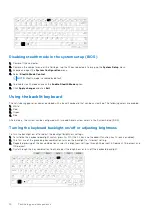
Страница 14: ...ed 1 White 2 Red 3 Green 4 Blue Alternatively the system can be configured with two additional custom colors in the System Setup BIOS Turning the keyboard backlight on off or adjusting brightness To turn the backlight on off or adjust the backlight brightness settings 1 To initialize the keyboard backlight switch press Fn F10 the Fn key is not needed if function key Fn lock is enabled 2 The first ...

Страница 15: ...Configuration menu select RGB Keyboard Backlight You can enable disable the standard colors White Red Green and Blue 4 To set a custom RGB value use the input boxes on the right side of the screen 5 Click Apply changes and click Exit to close System Setup Function Fn key lock features NOTE The keyboard has Function key Fn lock capability When activated the secondary functions on the top row of key...

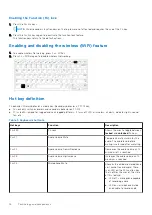
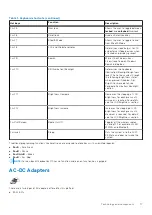
Страница 16: ...nd semi rugged platforms It turns off LCD all wireless all alerts indicator lights sound fan etc Table 1 Keyboard shortcuts Hot keys Function Description Fn ESC Fn Lock Allows the user to toggle between locked and unlocked Fn keys Fn F1 Audio Volume Mute Temporarily mutes unmutes the audio The audio level before muting is returned after unmuting Fn F2 Audio Volume Down Decrease Decreases the audio...

Страница 17: ...llumination Backlight section Fn F11 Brightness Decrease Decreases the stepping of LCD brightness for each press until minimum is reached For details see the LCD Brightness section Fn F12 Brightness Increase Increases the stepping of LCD brightness for each press until maximum is reached For details see the LCD Brightness section Fn PrintScreen Radio On Off Toggles all the wireless radios on and o...

Страница 18: ... connecting the cable to the power strip or electrical outlet may cause fire or equipment damage How to check the status of AC Adapter in BIOS 1 Restart Power on your computer 2 At the first text on the screen or when the Dell logo appears tap F2 until the message Entering Setup appears 3 Under General Battery Information you will see AC Adapter listed 4 The status shows the wattage of the AC adap...

Страница 19: ...130W Technology and components 19 ...

Страница 20: ...LED and Cable 20 Technology and components ...

Страница 21: ...s What is ExpressCharge For a system advertised as having the ExpressCharge feature the battery typically will have greater than 80 charge after about an hour of charging with the system off and fully charged in about 2 hours with the system off Enabling Expresscharge requires that both the system and the battery that is used on the system be ExpressCharge capable If any of the above requirements ...

Страница 22: ...ake also includes Core i7 i5 i3 Pentium and Celeron processors Skylake vs Broadwell roadmap The following illustration is a roadmap comparison between the Skylake processor vs the Broadwell processor Figure 2 Skylake vs Broadwell roadmap Processor performance features The following table illustrates the performance available on each Skylake suffix Table 3 Performance features Feature Feature descr...

Страница 23: ... Intel Built In Visuals Yes Yes Yes Compute OpenCL 2 0 Yes No yes Platform Hardware 14nm process Yes Yes Yes 16PCIe Graphic lanes configurable as 1x16 or 2x8 or 1x8 2x4 No No Yes PCIe Gen3 0 support No No Yes Switchable graphics muxless solution No Yes Yes Memory Memory Type DDR4 DDR4 DDR4 Connector Memory Down Memory down SODIMM SODIMM Speed 2133MT s for DDR4 2133MT s for DDR4 2133MT s for DDR4 M...

Страница 24: ...roller Intel Smart Cache Optional Intel vPro technology on i5 i7 with Active Management Technology 11 6 Intel Rapid Storage Technology Table 4 Kaby lake specifications Processor number Base Clock Speed Cache No of cores No of threads Power Memory type Graphics Intel Dual Core i3 7130U 2 7 GHz 3 MB 2 4 15 W DDR4 2400 Intel HD graphics 620 Intel Quad Core i5 8350U 1 7 GHz 6 MB 4 8 15 W DDR4 2400 Int...

Страница 25: ... the key notch on a DDR3 module Both notches are on the insertion edge but the notch location on the DDR4 is slightly different to prevent the module from being installed into an incompatible board or platform Figure 4 Notch difference Increased thickness DDR4 modules are slightly thicker than DDR3 to accommodate more signal layers Figure 5 Thickness difference Curved edge DDR4 modules feature a c...

Страница 26: ... DisplayPort 4096 2304 60 Hz AMD Radeon RX540 Discrete Intel Core i5 8350U Intel Core i7 8650U Discrete Dedicated 4 GB DDR5 HDMI 2 0 Additional video ports via Rear Configurable IO Space VGA DisplayPort 4096 2304 60 Hz NOTE Additional video ports via Rear Configurable IO Space is available with discrete graphics solution only Intel HD Graphics Integrated Intel HD graphics 620 This system can be co...

Страница 27: ...tegrated Graphics Controller Intel UHD Graphics 620 8th Generation Intel Core Bus Type Internal PCIe Memory Interface N A unified memory architecture Graphics Level GT2 Estimated Maximum Power Consumption TDP 15 W included in the CPU power Display Support On System HDMI 2 0 USB Type C Maximum Vertical Refresh Rate Up to 85 Hz depending on resolution Operating Systems Graphics Video API Support Dir...

Страница 28: ...nd or digital System ports Max Digital HDMI 4096x2304 24 Hz Analog VGA system 14 inches 15 inches or docking 2048x1152 60 Hz Docked Max Digital DisplayPort 1 2 3860 x2160 60 Hz Max Digital SL DVI 1920x1080 60 Hz Analog VGA system 14 inches 15 inches 2048x1152 60 Hz For 3 displays native or docked up to 1920x1200 max resolution each Numbers of Displays Supported System Ports 3 displays max with LCD...

Страница 29: ...s HDMI is limited to the older version 1 4a max 3840 x 2160 30 Hz However HDMI 2 0 can be added using a DisplayPort converter Up to three displays can be controlled simultaneously Power Consumption The HD Graphics 520 can be found in mobile processors specified at 15 W TDP and is therefore suited for compact laptops and Ultrabooks Key Specifications The following table contains the key specificati...

Страница 30: ... completely in hardware and more efficiently than before Displays can be connected using a DP 1 2 eDP 1 3 max 3840 x 2160 60 Hz whereas HDMI is limited to the older version 1 4a max 3840 x 2160 30 Hz However HDMI 2 0 can be added using a DisplayPort converter Up to three displays can be controlled simultaneously Power Consumption The HD Graphics 620 can be found in mobile processors specified at 1...

Страница 31: ...bits per pixel Maximum Vertical Refresh Rate Up to 85 Hz depending on resolution Operating Systems Graphics Video API Support DirectX 12 OpenGL 4 5 Supported Resolutions and Max Refresh Rates Hz Note Analog and or digital Single DisplayPort 1 4 5120 x 2880 60 Hz Dual DisplayPort 1 4 5120 x 2880 60 Hz Numbers of Display Support Up to five displays operating at 4096 x 2160 60 Hz AMD Radeon RX 540 Gr...

Страница 32: ...s research The new glass is just as thin and light as previous versions but has been formulated to deliver dramatically improved native damage resistance allowing improved in field performance Corning Gorilla Glass 5 has been tested for performance when subjected to sharp contact damage such as asphalt and other real world surfaces Benefits Enhanced retained strength after use High resistance to s...

Страница 33: ...ptical Refractive Index 590 nm Core glass 1 50 Compression layer 1 51 Photo elastic constant 30 3 nm cm MPa Core index is used for FSM based measurements since it is unaffected by ion exchange conditions Chemical Durability Durability is measured via weight loss per surface area after immersion in the solvents shown below Values are highly dependent upon actual testing conditions Data reported is ...

Страница 34: ...e electrostatic pen stylus or use your finger as an input device Using the Pen as a Mouse You can use the pen the same way you use a mouse or touch pad with a laptop computer Holding the pen near the display makes a small cursor appear Moving the pen moves the cursor The following table describes how to use the pen Table 18 Pen functions Action Function Gently tap the pen tip on the screen Same as...

Страница 35: ... you tap it the Input Panel opens at the same horizontal location on the screen that the tab appears Pen Flicks Pen flicks enable you to use the pen to perform actions that normally require a keyboard such as pressing Page Up or using the directional arrow keys Pen flicks are quick directional gestures Draw a short line in one of eight directions When a pen flick is recognized the Tablet PC perfor...

Страница 36: ...iB binary kilobytes 4482 625 megabytes MiB binary megabytes or 4 377563476 gibabytes GiB binary gigabytes DVD R also DVD R DVD plus dash R or DVD plus minus R is not a separate DVD format but rather is a shorthand term for a DVD drive that can accept both of the common recordable DVD formats i e DVD R and DVD R Likewise DVD RW also written as DVD R W DVD R RW DVD R RW DVD RW and other arbitrary wa...

Страница 37: ...s the same form factors as existing CD and DVD optical discs allowing for backwards compatibility Features Listed below are some of Blu ray s features Huge capacity 25 GB single layer 50 GB double layer NOTE All Dell Blu Ray drives support dual layer 50 GB discs However the new combo drives DVDRW BD ROM simply read dual layer discs but do not write to them Future potential to store 200 GB Multilay...

Страница 38: ...re are a few possible profiles for Blu ray they are Standard and BD Live Table 21 Blue ray Profiles Standard BD Live Not yet available Functionality Large back up device Blu ray video playback Blu ray video authoring Standard Profile Picture in Picture Internet connectivity Local storage System requirements Drive Graphics CPU combination sufficient to handle BD BD software Monitor Memory Standard ...

Страница 39: ...I BIOS unless the UEFI option is checked in the Boot List Option setting in the BIOS page This will allow the user to create a UEFI boot option list manually without affecting the existing boot priority list With the implementation of UEFI BIOS the changes are more related to the manufacturing tools and functionalities with very minimal impact to the customer s usages Few things to remember are If...

Страница 40: ...s with an extensive inventory of the hardware and health state data Admins can also configure hardware remotely by using command line and scripting Dell Command Update end user tool is factory installed and allows admins to individually manage and automatically present and install Dell updates to the BIOS drivers and software Command l Update eliminates the time consuming hunting and pecking proce...

Страница 41: ...ario Fingerprint Reader This topic explains the software used in fingerprint reader The Portables Technology has an integrated fingerprint reader located on the palm rest to the right of the touch pad The fingerprint reader is an option so not all systems have it Included with the driver for the fingerprint reader is a software package from Dell ControlVault that provides functionality for the dev...

Страница 42: ...some of the most commonly asked questions regarding USB 3 0 USB 3 1 Gen 1 Speed Currently there are 3 speed modes defined by the latest USB 3 0 USB 3 1 Gen 1 specification They are Super Speed Hi Speed and Full Speed The new SuperSpeed mode has a transfer rate of 4 8 Gbps While the specification retains Hi Speed and Full Speed USB mode commonly known as USB 2 0 and 1 1 respectively the slower mode...

Страница 43: ...USB 3 1 Gen 1 products External Desktop USB 3 0 USB 3 1 Gen 1 Hard Drives Portable USB 3 0 USB 3 1 Gen 1 Hard Drives USB 3 0 USB 3 1 Gen 1 Drive Docks Adapters USB 3 0 USB 3 1 Gen 1 Flash Drives Readers USB 3 0 USB 3 1 Gen 1 Solid state Drives USB 3 0 USB 3 1 Gen 1 RAIDs Optical Media Drives Multimedia Devices Networking USB 3 0 USB 3 1 Gen 1 Adapter Cards Hubs Compatibility The good news is that ...

Страница 44: ...l the end of all those proprietary laptop charging cables with everything charging via a standard USB connection You could charge your laptop from one of those portable battery packs you charge your smartphones and other portable devices from today You could plug your laptop into an external display connected to a power cable and that external display would charge your laptop as you used it as an ...

Страница 45: ...02 1as 1588 conformance Power Optimizer Support Intel Stable Image Platform Program SIPP Network proxy ARP Offload support Up to 32 programmable filters No support for Gb s half duplex operation Security and Manageability Intel vPro support with appropriate Intel chipset components Performance Jumbo Frames up to 9 Kb 802 1Q 802 1p Receive Side Scaling RSS Two Queues Tx Rx Power Ultra Low Power at ...

Страница 46: ...rs to take full advantage of their IP enabled devices without a separate Ethernet cable Audio Return Channel Allows an HDMI connected TV with a built in tuner to send audio data upstream to a surround audio system eliminating the need for a separate audio cable 3D Defines input output protocols for major 3D video formats paving the way for true 3D gaming and 3D home theater applications Content Ty...

Страница 47: ...es currently used in A V systems HDMI supports communication between the video source such as a DVD player and the DTV enabling new functionality Software and Troubleshooting Chipsets All laptops or notebook communicate with the CPU through the chipset This laptop is shipped with the Intel Sky Lake or Kaby Lake chipset Identifying the chipset in Device Manager on Windows 10 1 Click All Settings on...

Страница 48: ...uter and then click Submit NOTE If you do not have the Service Tag use the autodetect feature or manually browse for your computer model 4 Click Drivers and Downloads 5 Select the operating system installed in your computer 6 Scroll down the page expand Chipset and select your chipset driver 7 Click Download File to download the latest version of the chipset driver for your computer 8 After the do...

Страница 49: ...f the processor is displayed Verifying the processor usage in Task Manager 1 Press and hold the taskbar 2 Select Start Task Manager The Windows Task Manager window is displayed 3 Click the Performance tab in the Windows Task Manager window The processor performance details are displayed Verifying the processor usage in Resource Monitor 1 Press and hold the taskbar 2 Select Start Task Manager The W...

Страница 50: ...Dell logo is displayed With keyboard Tap F2 until the Entering BIOS setup message appears To enter the Boot selection menu tap F12 3 On the left pane select Settings General System Information The memory information is displayed on the right pane Testing memory using ePSA 1 Turn on or restart your system 2 Perform one of the following actions after the Dell logo is displayed With keyboard press F1...

Страница 51: ...apter 1 On the taskbar click or tap the search box and then type Device Manger 2 Click or tap Device Manager The Device Manager window is displayed 3 Expand Display adapters Figure 7 Display adapters Downloading drivers 1 Turn on the laptop 2 Go to Dell com support 3 Click Product Support enter the Service Tag of your laptop and then click Submit NOTE If you do not have the Service Tag use the aut...

Страница 52: ...tic screen brightness adjustment 1 Click Start Control Panel Display 2 Use the Adjust brightness slider to enable or disable automatic brightness adjustment NOTE You can also use the Brightness level slider to adjust the brightness manually Changing the screen resolution 1 Press and hold the desktop screen and select Display Settings 2 Tap or click Advanced display settings 3 Select the required r...

Страница 53: ...n Clear the box to disable the touch screen Touchscreen Troubleshooting If the touchscreen is not able to access items along the edges of the LCD it may need to be calibrated To calibrate the touchscreen complete the following steps Touchscreen Calibration Start Control Panel Tablet PC Settings choose Calibrate You can choose to calibrate Pen input or Touch input Perform the point calibrations tha...

Страница 54: ...e display dry thoroughly before you turn it on 7 For stains that are hard to remove repeat this procedure till the display is clean Troubleshooting Touchpad Most touch pad issues are erratic movement or no movement at all Since erratic movement is the more common problem it is covered first Erratic Pointer Movement Here are some easy steps to take to determine the problem with a touch pad demonstr...

Страница 55: ...form the following steps 1 Verify the pen tip is in good shape free of chips excessive wear etc 2 Replace the pen tip with a new one or the one that is in good condition 3 Verify that the touch capabilities are not affected 4 Switch to touch mode and see if the problem still exists 5 If no symptoms persist in touch mode the pen tip is the most likely suspect 6 If the problem does persist in touch ...

Страница 56: ...nloading the latest version from Microsoft 4 See if the problem occurs on both internal and external speakers If isolated to only one of the two follow the troubleshooting mentioned above Otherwise run Dell Diagnostics to test the audio 5 If the problem fails during the audio test this is a hardware problem and the system needs service If it does not then a software problem exists Sound from Only ...

Страница 57: ... that uses the camera For instance if you tap the Skype software that is shipped with the laptop the camera turns on Similarly if you are chatting on the internet and the application requests to access the webcam the webcam turns on Starting the camera application 1 Tap or click the Windows button and select All apps 2 Select Camera from the apps list Technology and components 57 ...

Страница 58: ...for it Hard drive options This laptop supports M 2 SATA drives Identifying the hard drive in Windows 10 1 Tap or click All Settings on the Windows 10 Charms Bar 2 Tap or click Control Panel select Device Manager and expand Disk drives 58 Technology and components ...
Страница 59: ...ter the Boot selection menu tap F12 The hard drive is listed under the System Information under the General group Dell Command Configure Dell Command Configure Command Configure is a packaged software offering that provides configuration capability to business client platforms This product consists of a Command Line Interface CLI and Graphical User Interface GUI to configure various BIOS features ...

Страница 60: ...Dell Precision Workstation Mobile Dell Precision Workstation NOTE Dell Command Configure will not be pre loaded for the customer upon purchase Customers will be able to download the software from the Dell support website Command Configure Graphical User Interface The Dell Command Configure Graphical User Interface Command Configure GUI displays all Basic Input Output System BIOS configurations sup...

Страница 61: ...d Configure GUI Command Configure WINPE Allows access to the Windows PE scripts to create a bootable image For more details see the Dell Command Configure Installation Guide Uninstall Uninstalls Command Configure User s Guide Online Provides access to the Command Configure online documentation Launching The Command Configure GUI NOTE The Command Configure GUI is supported only on systems running t...

Страница 62: ...tart All Program Dell Command Configure Command Configure Command Prompt 2 Navigate to the x86 or x86_64 directory depending on the architecture of the operating system 3 Run the Command Configure commands Bootable Image To run Command Configure commands 1 Copy Dell Command Configure with the International Organization for Standardization ISO image to a Compact Disc CD For more information see Del...

Страница 63: ...ntel HD Graphics drivers Verify if the Intel HD Graphics drivers are already installed in the laptop Table 26 Intel HD Graphics drivers Before installation After installation Technology and components 63 ...

Страница 64: ...y Microphone Camera Battery Bay Left I O board Smart Card ExpressCard Reader Speaker System board Bottom Base Assembly Safety instructions Use the following safety guidelines to protect your computer from potential damage and to ensure your personal safety Unless otherwise noted each procedure included in this document assumes that the following conditions exist You have read the safety informatio...

Страница 65: ...ment Before working inside your computer 1 Ensure that your work surface is flat and clean to prevent the computer cover from being scratched 2 Turn off your computer 3 If the computer is connected to a docking device docked undock it 4 Disconnect all network cables from the computer if available CAUTION If your computer has an RJ45 port disconnect the network cable by first unplugging the cable f...

Страница 66: ...easing concern Due to the increased density of semiconductors used in recent Dell products the sensitivity to static damage is now higher than in earlier Dell products For this reason some previously approved methods of handling parts are no longer applicable There are two recognized types of ESD damage catastrophic and intermittent failures Catastrophic The damage causes an immediate and complete...

Страница 67: ...nd workbench pads When handling static sensitive components grasp them by the sides not the top Avoid touching pins and circuit boards When unpacking a static sensitive component from its shipping carton do not remove the component from the anti static packing material until you are ready to install the component Before unwrapping the anti static packaging be sure to discharge static electricity f...

Страница 68: ...ire can be either directly connected between your wrist and bare metal on the hardware if the ESD mat is not required or connected to the anti static mat to protect hardware that is temporarily placed on the mat The physical connection of the wrist strap and bonding wire between your skin the ESD mat and the hardware is known as bonding Use only Field Service kits with a wrist strap mat and bondin...

Страница 69: ...you do not have your own wrist strap tester check with your regional office to find out if they have one To perform the test plug the wrist strap s bonding wire into the tester while it is strapped to your wrist and push the button to test A green LED is lit if the test is successful a red LED is lit and an alarm sounds if the test fails Figure 13 Wrist Strap Tester Insulator Elements It is critic...

Страница 70: ...ors that can cause an ESD event On the work area insulators such as Styrofoam and other plastics should always be moved at least 12 inches or 30 centimeters away from sensitive parts before physically handling any hardware components ESD Packaging All ESD sensitive devices must be shipped and received in static safe packaging Metal static shielded bags are preferred However you should always retur...

Страница 71: ...nents Lifting Equipment NOTE Do not lift greater than 50 pounds Always obtain assistance from another person or persons or use a mechanical lifting device Adhere to the following guidelines when lifting equipment 1 Get a firm balanced footing Keep your feet apart for a stable base and point your toes out 2 Bend your knees Do not bend at the waist 3 Tighten stomach muscles Abdominal muscles support...

Страница 72: ...Connect any telephone or network cables to your computer CAUTION To connect a network cable first plug the cable into the network device and then plug it into the computer 3 Connect your computer and all attached devices to their electrical outlets 4 Turn on your computer Recommended tools The procedures in this document require the following tools Phillips 0 screwdriver Phillips 1 screwdriver Pla...

Страница 73: ...2 Withdraw the stylus out of the slot Installing the stylus 1 Insert the stylus in the slot Removing and installing components 73 ...

Страница 74: ...2 Close the I O door 1 and press the door until it latches 2 SIM card Removing the SIM card 1 Remove the SIM card out of the slot on the system board 74 Removing and installing components ...

Страница 75: ...ure in After working inside your computer Installing the SIM card 1 Follow the procedure in Before working inside your computer 2 Open the right I O door 3 Insert the SIM card into the slot on the system board Removing and installing components 75 ...

Страница 76: ...g the memory card 1 Open the right I O door 2 Insert the memory card in the slot on the system board Removing the memory card 1 Remove the memory card from the slot on the system board 76 Removing and installing components ...

Страница 77: ...uire additional focus These screws are difficult to remove and can be damaged during the removal process To prevent damage to the screws and surrounding plastics use the correct screwdriver for each screw type Remove the two epoxy M3 5 7 screws 1 that secures the handle to the computer 3 Separate the handle from the computer 2 Removing and installing components 77 ...

Страница 78: ...ndle 1 Install the handle on the computer 1 2 Tighten the two epoxy M3 5 7 screws 2 securing the handle to the computer 3 Follow the procedure in After working inside your computer 78 Removing and installing components ...

Страница 79: ...mputer 2 Open the I O door 3 Remove the screws 1 securing door hinges to the computer and lift the I O door 2 away from the computer Installing the latch doors 1 Install the door on the computer 1 2 Install the screws securing door hinges to the computer 2 Removing and installing components 79 ...

Страница 80: ...lation and removal procedure Follow the procedure in Before working inside your computer 2 Unlock the battery 1 and slide the latch along the groove to disengage locking mechanism 3 Pry on the recess point 2 and slide the battery forward 3 to remove it from the computer Installing the Batteries 1 Slide in the battery in battery bay to align the battery contacts 1 with one on the computer 2 Press t...

Страница 81: ...the same installation and removal procedure Secondary SSD carrier Removing the Secondary SSD carrier 1 Follow the procedure in Before working inside your computer 2 Open the right I O door 3 Release the SSD carrier by sliding the blue hard drive release latch towards left 1 4 Pull the SSD carrier out of the system using the blue tab 2 Removing and installing components 81 ...

Страница 82: ...ter 2 Push the carrier in the slot until blue tab clicks and close the right I O door 2 3 Follow the procedure in After working inside your computer Primary SSD carrier Removing the Primary SSD carrier 1 Follow the procedure in Before working inside your computer 82 Removing and installing components ...

Страница 83: ...elease latch 1 towards right 4 Slide the SSD carrier out of the computer using the blue pull tab 2 out of the computer Installing the Primary SSD carrier 1 Insert the primary SSD carrier 1 in to the computer 2 Push the carrier into the slot until the blue tab clicks and close the right I O door 2 3 Install the Batteries 4 Follow the procedure in After working inside your computer Removing and inst...

Страница 84: ...SD and interposer 1 from the SSD carrier tray 6 Flip over the assembly 2 and disconnect the SSD from the interposer 3 Installing the SSD in carrier 1 Connect the SSD to the interposer 1 flip over 2 2 Install the SSD with interposer on the SSD carrier tray preassembled with new thermal pad 3 3 Install the cover 1 on the SSD carrier and install the single M2 5 screw 2 4 Flip over the SSD carrier 3 a...

Страница 85: ...atteries 3 Press the blue latch 1 and slid the HDD carrier out of the slot on the system 2 4 NOTE Depending on the configuration ordered the system may have a Hard Drive or a Solid State Drive in the carrier The installation and removal procedure remains same Remove the six screws 1 and lift the cover from the top of the carrier 2 5 Remove the single screw 3 and slid the SSD out of the carrier 4 R...

Страница 86: ...1 Slide the SSD in the carrier 1 and secure it using the single screw 2 2 Secure the cover on the carrier 3 and tighten the six screws 4 3 Slide the HDD carrier in the slot 1 and close the IO door 2 86 Removing and installing components ...

Страница 87: ...g inside your computer 2 Remove the a Batteries 3 Unlock 1 and open the left right and rear I O door 2 4 Remove the 19 M2 5 5 screws on the bottom chassis cover 1 two M2 5 6 screws 2 in the rear I O space 5 Remove the bottom chassis cover 3 from the computer Removing and installing components 87 ...

Страница 88: ...sis Cover 1 Install the bottom chassis cover over the bottom base 1 of the computer 2 Install the two M2 5 6 screws 2 in the rear I O space and 19 M2 5 5 screws 3 on the bottom chassis cover 88 Removing and installing components ...

Страница 89: ...3 Close the left right and rear I O doors 4 Install the a Batteries 5 Follow the procedure in After working inside your computer Removing and installing components 89 ...

Страница 90: ... 3 Remove the six M2 5 5 screws on the keyboard 1 and pry at the bottom edge of the keyboard 2 4 Slide the keyboard slightly 1 towards touch pad and flip it over inclined over the LCD panel 2 5 Remove the four M2 3 screws 1 on the keyboard cover and remove it from the computer 2 90 Removing and installing components ...

Страница 91: ...cess the keyboard and back light FPC connectors on the system board 7 Separate the keyboard from the system 3 Installing the Keyboard 1 Install the keyboard 1 and connect the keyboard and back light FPC to the system board 2 2 Secure keyboard and back light FPC connections using an insulation tape 3 Removing and installing components 91 ...

Страница 92: ...ard cover 1 and tighten the four M2 3 screws 2 to secure it to the chassis 4 Flip the keyboard 3 over on the chassis 3 5 Slide the keyboard towards LCD 1 to align it to screw holes 2 92 Removing and installing components ...

Страница 93: ...Removing the WWAN card 1 Follow the procedure in Before working inside your computer 2 Remove the a Batteries b Bottom chassis cover 3 Remove the single M2 3 screw 1 remove the metal bracket 2 on the WWAN card 4 Disconnect the antennae cables 3 and remove the WWAN card 4 out of the M 2 slot on the system board Removing and installing components 93 ...

Страница 94: ...lot 1 on the system board and connect the antennae cables 2 2 Secure the WWAN card using the metal bracket 3 and tighten the single M2 3 screw 4 securing the WWAN card to the system board 3 Install the a Bottom chassis cover 94 Removing and installing components ...

Страница 95: ... the single M2 3 screw 1 and remove the metal bracket 2 on the WLAN card 4 Disconnect the antennae cables 3 and remove the WLAN card out from the M 2 slot 4 on the system board Installing the WLAN card 1 Install the WLAN card into the M 2 slot 1 on the system board and connect the antennae cables 2 2 Place the metal bracket on the WLAN card 3 and secure it using the single M2 3 screw 4 Removing an...

Страница 96: ...the procedure in Before working inside your computer 2 Remove the a Batteries b Bottom chassis cover c Rear I O board 3 Unroute the aux cables 1 for WLAN and WWAN and disconnect the antennae cable 2 on GPS module 4 Unroute the main antennae cables 3 and loosen the single M2 5 5 screw 4 to separate the RF bracket 5 from the system board 96 Removing and installing components ...

Страница 97: ... two M2 5 5 screws 3 and separate the GPS module 4 from the system board Installing the GPS module 1 Align and place the GPS module on the system board and tighten the two M2 5 5 screws on GPS module 2 2 Connect the GPS FPC system board side first 3 and secure it using a piece of tape 4 Removing and installing components 97 ...

Страница 98: ...for WLAN and WWAN cards through the RF bracket 3 5 Connect the antennae cable 4 on GPS module and route the main antennae cables 5 through the RF bracket 6 Install the a Rear I O board b Bottom Chassis Cover c Batteries 7 Follow the procedure in After working inside your computer 98 Removing and installing components ...

Страница 99: ... 3 Pull the clips securing the memory module 1 until the socket disengages and remove the memory module from the memory socket 2 on the system board Installing the Memory 1 Align and insert the memory module along the keyed notch 1 at an acute angle and press the memory module 2 until securing clips engages Removing and installing components 99 ...

Страница 100: ...n Before working inside your computer 2 Remove the a Bottom chassis cover b Batteries 3 NOTE Removing or Disconnecting the coin cell may reset systemboard BIOS system time to defaults or engage bit locker or other similar security protocol devices Disconnect the coin cell connector from the system board 1 and remove it from the system 2 100 Removing and installing components ...

Страница 101: ...nstall the coin cell 1 and connect the coin cell connector to the system board 2 2 Install the a Bottom chassis cover b Batteries 3 Follow the procedure in After working inside your computer Removing and installing components 101 ...

Страница 102: ...b Bottom chassis cover 3 Disconnect the fan cable 1 from the system board 4 Remove the seven M2 5 5 screws 2 from the heat sink pipe and loosen the three captive screws from fan case 3 5 Remove the PCIe heatsink fan assembly from the computer 4 6 Remove the four M2 3 screws 1 to separate the heatsink from the fan 2 102 Removing and installing components ...

Страница 103: ...Installing the PCIe heatsink fan assembly 1 Replace the fan to th heatsink assembly 1 and secure it using four M2 3 screws 2 Removing and installing components 103 ...

Страница 104: ...1 in the chassis and tighten the three captive screws 2 on the fan case 3 Install the seven M2 5 screws 3 on the heat sink pipe and connect the fan cable 4 4 Install the a Bottom chassis cover b Batteries 104 Removing and installing components ...

Страница 105: ... assembly 3 Peel off the inductive tape on the SSD FPC connector 1 on system board and disconnect it 2 4 Remove the 4 M2 3 screws 3 and remove it from the computer 4 Installing the Primary SSD rail 1 Install the primary SSD rail on the system board 1 and tighten the four M2 3 screws 2 securing it to the system board 2 Connect the SSD FPC connector 3 to the system board and secure it using a piece ...

Страница 106: ...ing inside your computer Docking Port Assembly Removing the Docking port assembly 1 Follow the procedure in Before working inside your computer 2 Remove the a Batteries b Bottom chassis cover c PCIe Heatsink assembly 3 Peel off the tape securing the dock FPC 1 and disconnect the dock FPC 2 106 Removing and installing components ...

Страница 107: ...RF passthrough connectors 1 and unroute the antennae cables 2 from the routing channels on the dock assembly 5 Remove the two M2 5 5 screws 1 and separate the docking board assembly from the chassis 2 Removing and installing components 107 ...

Страница 108: ...g Port Assembly 1 Install the docking port assembly 1 and install the two M2 5 5 screws 2 securing it to the system board 2 Connect the dock FPC 1 and secure it using a piece of tape 2 108 Removing and installing components ...

Страница 109: ... channels 1 and connect the antennae cables on RF passthrough connectors 2 4 Install the a PCIe Heatsink assembly b Batteries c Bottom chassis cover 5 Follow the procedure in After working inside your computer Removing and installing components 109 ...

Страница 110: ...ries b Bottom chassis cover c WLAN card d WWAN card e PCIe Heatsink fan assembly f Docking port assembly 3 NOTE Depending on the order configuration details the system may have either of the heatsink assembly DSC Heatsink assembly Unroute the antennae cables from the tabs on the heatsink pipe 110 Removing and installing components ...

Страница 111: ...creet and UMA bases have different types of heatsink assembly Installing the Heatsink assembly 1 Install the heatsink assembly 1 in the computer and tighten the two M1 6 5 2 screw near the CPU 2 Install the five M2 5 5 captive screws 3 on the thermal module securing the thermal module to the system board Removing and installing components 111 ...

Страница 112: ...hannel on the heatsink pipe 4 Install the a Docking port assembly b PCIe Heatsink assembly c WWAN card d WLAN card e Bottom chassis cover f Batteries 5 Follow the procedure in After working inside your computer 112 Removing and installing components ...

Страница 113: ...owing epoxy screw locations will require additional focus These screws are difficult to remove and there may be damage during the removal process To prevent damage to the screws and surrounding plastics please use the correct screwdriver for each screw type 3 Peel off the inductive tape on the I O board FPC connector 1 to disconnect it from the system board 2 4 Remove the two epoxy cap screws on t...

Страница 114: ...rough the face plate 1 2 Secure the I O board using three M2 5 5 screws 2 3 Tighten the two epoxy cap screws on the serial port 1 in the rear I O space 4 Connect the I O board FPC 2 to the system board and then to I O board itself 3 and secure it using a piece of tape 3 114 Removing and installing components ...

Страница 115: ...procedure in After working inside your computer Hinge Covers Removing the Hinge Covers 1 Follow the procedure in Before working inside your computer 2 Remove the a Batteries b Bottom chassis cover c Heatsink 3 Remove the two M2 5 5 on either sides 1 and lift to remove the brackets 2 from the computer Removing and installing components 115 ...

Страница 116: ...4 Press the latch 1 and open the LCD lid 2 5 Hold the LCD lid at an obtuse angle and push the hinge covers from the rear end to remove it from the computer 116 Removing and installing components ...

Страница 117: ...ing the Hinge Covers 1 Press the latch 1 and open the LCD lid 2 2 Keep LCD lid open at an obtuse angle and insert the hinge covers from front until it clicks in its place Removing and installing components 117 ...

Страница 118: ...ckets 1 and secure it using two M2 5 5 on either sides 2 4 Install the a Heatsink b Bottom chassis cover c Batteries 5 Follow the procedure in After working inside your computer 118 Removing and installing components ...

Страница 119: ... the EDP bracket and turn it up side down 2 4 CAUTION The following epoxy screw locations will require additional focus These screws are difficult to remove and there may be damage during the removal process To prevent damage to the screws and surrounding plastics please use the correct screwdriver for each screw type Pull and disconnect the EDP cable from the system board 3 and remove the two M2 ...

Страница 120: ... To prevent damage to the screws and surrounding plastics please use the correct screwdriver for each screw type Loosen the four epoxy screws on hinges 1 and to separate the LCD assembly from the computer 2 Installing the Display Assembly 1 Tighten the two epoxy screws on left 1 and on the right 2 side and 2 Close the lid 3 120 Removing and installing components ...

Страница 121: ...o base assembly 1 and rethread the antennae cables 2 4 Connect the EDP cable 3 to the system board and place the EDP bracket over the cable 4 5 Install the two M2 3 screws 5 and secure the EDP bracket to the system board Removing and installing components 121 ...

Страница 122: ...uter LCD Bezel and Back Cover Assembly Removing the LCD with bezel and the display back cover assembly 1 Follow the procedure in Before working inside your computer 2 Remove the a Batteries b Bottom chassis cover c WLAN card d WWAN card e PCIe heatsink assembly f Docking port assembly g Heatsink h Hinge covers i Display assembly 3 Loosen the 12 M2 5 screws from the back cover 122 Removing and inst...

Страница 123: ...rrect screwdriver for each screw type Remove the four M2 5 epoxy screws securing the bezel to the back cover 1 and pry at bottom edge to separate the two subassemblies 2 5 Peel off the tape on the LCD connections 1 and open the connector 2 to disconnect the EDP cable 3 from the LCD 6 Peel off the reflective tape 4 on the LCD panel and the touch connector 5 and disconnect the cable from the board 6...

Страница 124: ...actuator 2 2 Secure the connector using a piece of tape 3 and adhere the reflective tape on the display panel 4 3 Connect the touch controller cable 5 and use insulation tape on the connector 6 4 Align and place the bezel on the back cover 1 and secure it using the four M2 5 epoxy screws 2 124 Removing and installing components ...

Страница 125: ... assembly 6 Install the a Display assembly b Hinge covers c Heatsink d PCIe heatsink assembly e Docking port assembly f WWAN card g WLAN card h Bottom chassis cover i Batteries 7 Follow the procedure in After working inside your computer Removing and installing components 125 ...

Страница 126: ... f PCIe heatsink assembly g Docking port assembly h Heatsink i Hinge covers j Display assembly k LCD bezel and back cover assembly 3 Peel off the tape securing the microphone daughterboard 1 and remove the two M2 3 screws 2 to turn the daughterboard 3 up side down 4 Peel off the insulation tape 1 and disconnect the EDP cable connectors 2 126 Removing and installing components ...

Страница 127: ...1 and secure it using a piece of tape 2 2 Turn over the microphone daughterboard on the back cover 1 and tighten the two M2 3 screws 2 3 Secure the microphone daughterboard using a piece of reflective tape on either sides 3 to the LCD back cover Removing and installing components 127 ...

Страница 128: ...ocedure in Before working inside your computer 2 Remove the a Batteries b Bottom chassis cover c Memory d WLAN card e WWAN card f PCIe heatsink assembly g Docking port assembly h Heatsink i Hinge covers j Display assembly k LCD Bezel and back cover assembly 3 Peel off the reflective tape 1 on camera module and the insulation tape securing the EDP cable 2 to camera module 4 Disconnect the EDP cable...

Страница 129: ... 1 Install the camera module 1 on the back cover and install the two M2 3 screws 2 2 Connect the EDP cable to the camera module 3 stick a piece of insulation tape 4 on the EDP connectors 3 Secure the camera module on the back cover using a piece of reflective tape 5 4 Install the a LCD with bezel assembly b Display assembly c Hinge covers Removing and installing components 129 ...

Страница 130: ... computer 2 Remove the a Batteries b Bottom chassis cover c PCIe Heatsink assembly 3 CAUTION Use extreme caution when removing cable due to the very limited space cable could be easily pinched or bent leading to cable damage Disconnect both the battery connections from the system board 4 Remove the five M2 5 5 1 and nine M2 5 3 2 screws securing the battery bay to chassis and lift to separate the ...

Страница 131: ...attery bay 1 Install the battery bay 1 on the computer and tighten the five M2 5 5 2 and nine M2 5 3 3 securing it to the chassis 2 Connect the battery cables to the system board Removing and installing components 131 ...

Страница 132: ... O daughterboard 1 Follow the procedure in Before working inside your computer 2 Remove the a Batteries b Bottom chassis cover c PCIe Heatsink fan assembly d Battery bay 3 Peel off the tape 1 disconnect the left I O daughterboard FPC connector 2 from the system board 4 Disconnect the speaker cable from the left I O daughterboard 3 132 Removing and installing components ...

Страница 133: ...ews 1 and lift the Left I O daughterboard from the computer 2 Installing the Left I O Board 1 Install the left I O daughterboard 1 and secure it using the two M2 3 screws 2 to the computer Removing and installing components 133 ...

Страница 134: ...f insulation tape 2 3 Connect the speaker cable to the left I O daughterboard 3 4 Install the a Battery bay b PCIe Heatsink fan assembly c Bottom chassis cover d Batteries 5 Follow the procedure in After working inside your computer 134 Removing and installing components ...

Страница 135: ...eatsink assembly d Battery bay 3 Remove the tape from the smart card reader connector 1 and disconnect it 2 from the USH board 4 Remove the tape from the fingerprint reader connector 3 and disconnect it from the USH board 4 5 Remove the two M2 3 screws 1 securing the USH board to the bottom base and turn it up side down 2 Removing and installing components 135 ...

Страница 136: ...ve the tape 1 and disconnect the Smartcard Reader FPC connector 2 from the USH board 7 Loosen the four M2 3 screws 1 and remove the smart card 2 reader from the computer 136 Removing and installing components ...

Страница 137: ... card reader through the I O face plate 1 and install the four M2 3 screws to secure it to the bottom chassis 2 2 Connect the Smart Card FPC on the underside of the USH board 1 and secure it using a piece of tape 2 Removing and installing components 137 ...

Страница 138: ...USH board to secure it to the chassis 2 4 Connect the smart card FPC connector 1 and securing it with a piece of tape 2 5 Connect the finger print reader FPC 3 and secure it using a piece of tap 4 to the USH board 138 Removing and installing components ...

Страница 139: ...ard Reader Removing the ExpressCard Reader 1 Follow the procedure in Before working inside your computer 2 Remove the a Batteries b Bottom chassis cover c PCIe heatsink assembly d Battery bay e Left I O daughterboard f Smart card 3 Peel off the tape on express card FPC connector 1 and disconnect it 2 from system board Removing and installing components 139 ...

Страница 140: ...aceplate and the six M2 5 screws securing the Smart card to the computer 1 5 Lift and remove the express card up to remove it from the computer 2 6 Separate the express card reader from the face plate 140 Removing and installing components ...

Страница 141: ...place the Express Card reader 1 on the computer and secure the face plate with two screws 3 Install the four M2 5 screws securing the Express Card reader to the computer 2 4 Connect the express card FPC cable to the system board 1 and secure it using a piece of tape 2 Removing and installing components 141 ...

Страница 142: ... inside your computer Speaker Removing the Speaker 1 Follow the procedure in Before working inside your computer 2 Remove the a Batteries b Bottom chassis cover c PCIe heatsink assembly d Left I O daughterboard e Battery bay 3 Remove the two M2 5 7 screws 1 and remove the speaker from the computer 2 142 Removing and installing components ...

Страница 143: ...two M2 5 7 screws to secure the speaker to the base 2 2 Install the a Battery Bay b Left I O daughterboard c PCIe Heatsink assembly d Docking port assembly e Bottom Chassis Cover f Batteries 3 Follow the procedure in After working inside your computer Removing and installing components 143 ...

Страница 144: ...t Sink i Memory j WLAN card k WWAN card l GPS module m Primary SSD rail n Battery bay o Rear I O board 3 Peel off the tape 1 disconnect and lift the SSD ODD assembly 2 from the system board 4 Peel off the tape 3 from touch pad connectors and disconnect it from the system board 4 5 Peel off the tape 1 and disconnect the rear I O board FPC connector 2 from the system board 6 Peel off the tape 3 and ...

Страница 145: ... 3 and disconnect the express card FPC 4 from the system board 10 Peel off the tape 1 and disconnect the power button FPC connector 2 from the system board 11 Peel off the tape 3 and disconnect the USH board FPC and touch pad connectors 4 from the system board Removing and installing components 145 ...

Страница 146: ...P cable 3 and disconnect the DC In connector 4 from the system board 14 Remove the two M2 5 5 screws and two M1 6 3 0 screws 1 from the USB Type C bracket 15 Remove the USB Type C bracket 2 and the two cap screws in the rear I O space 3 from the system board 146 Removing and installing components ...

Страница 147: ...e system board 3 from the computer Installing the System board 1 Install the system board inserting the serial port on the system board through chassis 1 and install the eight M2 5 screws 2 and single M2 3 screw epoxy screw 3 on the system board Removing and installing components 147 ...

Страница 148: ...I O FPC and Express Card reader FPC are not pinched under the System Board Install the USB Type C bracket 2 and secure it with two M2 5 5 screws and two M1 6 3 0 screws on the system board 3 4 Connect the EDP cable 1 and install the EDP bracket on the system board 2 5 Install the two M2 3 screws 3 on the EDP bracket and connect the DC In cable to the system board 4 148 Removing and installing comp...

Страница 149: ... 7 Connect the USH board and touch pad cables 3 to the system board and secure it using a piece of tape 4 8 Connect the left I O FPC cable 1 and secure it using a piece of tape 2 9 Connect the express card FPC cable 3 and secure it using a piece of tape 4 Removing and installing components 149 ...

Страница 150: ...C cable 3 and secure it using a piece of tape 4 12 Connect the docking port FPC cable 5 and secure it using a piece of tape 6 13 Connect the touch pad connectors to the system board 1 and secure it using a tape 2 14 Connect the SSD ODD assembly 3 and secure it using a piece of tape 4 150 Removing and installing components ...

Страница 151: ...teries 16 Follow the procedure in After working inside your computer Bottom Base Assembly 1 Follow the procedure in Before working inside your computer 2 To replace the bottom base assembly remove the following components from old base a Handle b Latched Doors c Batteries d Secondary SSD e Primary SSD f Hard Drive carrier g Bottom chassis cover h Keyboard i WWAN card j WLAN card k GPS module l Mem...

Страница 152: ...specifics of subcomponents defined in the Bottom Chassis Assembly NOTE The Latitude 5424 shipped with no ODD has the blank fused to the chassis Replace the Base Assembly for any issues with the power button or ODD or secondary SSD 4 Install the following components to the new base a System board b Express Card c Smart card d Left I O board e Battery Bay f Primary SSD rail g Display assembly h Rear...

Страница 153: ... q WWAN card r Keyboard s Bottom chassis cover t Hard Drive carrier u Primary SSD v Secondary SSD w Batteries x Latched doors y Handle 5 Follow the procedure in After working inside your computer Removing and installing components 153 ...

Страница 154: ...form you of problems encountered during testing NOTE The Enhanced Pre boot System Assessment window displays listing all devices detected in the computer The diagnostics starts running the tests on all the detected devices Running ePSA diagnostics Invoke diagnostics by either of the methods that are suggested below Tap F12 key on keyboard as the Dell splash screen appears until you get the message...

Страница 155: ... and contains more detailed information about the overall health of the system The user can get to this screen by simply swiping a finger to the left on touchscreen systems or clicking the next page button on the lower right hand side of the basic screen Diagnostics 155 ...

Страница 156: ...sc and click Yes to stop the diagnostic test 2 Select the device from the left pane and click Run Tests or use Advanced Option to include or exclude any test ePSA Error Messages When the Dell ePSA Diagnostic detects an error while running it will pause the test and the following window is displayed 156 Diagnostics ...

Страница 157: ...or by clicking on at the bottom right side of the error window NOTE Some tests for specific devices require user interaction Always ensure that you are present before the computer when the diagnostic tests are performed Validation Tools This section contains information on how to validate the SupportAssist ePSA ePSA or PSA error codes Error code verification can be done using below two methods Onl...

Страница 158: ...Enter error code validation code and service tag Part serial number is optional NOTE For error code use only the last 3 or 4 digits of the code user can enter 0142 or 142 instead of 2000 0142 4 Click on Submit once all the necessary information is entered 158 Diagnostics ...

Страница 159: ...ple After entering the correct information the online tools will direct the user to the above screen which contains information on Confirmation of the error code and result outcome Suggested Part Replacement Diagnostics 159 ...

Страница 160: ...mple QR APP Validation Tool Besides using the online tool customers can also validate the error code by scanning the QR code with a QR APP on a smartphone 1 User to obtain the QR code from SupportAssist On board Diagnostics error screen 2 User can use any QR code scanner application through the smartphone to scan the QR code 160 Diagnostics ...

Страница 161: ...3 The QR code scanner application will scan the code and automatically generate a link Click the link to proceed Diagnostics 161 ...

Страница 162: ...Support website which contains information on Confirmation of the error code and result outcome Suggested Part Replacement If customer is still covered under Dell Warranty Case reference number if there is an open case under the service tag 162 Diagnostics ...

Страница 163: ...wer off the Dell laptop 2 Disconnect any peripherals that are connected to the laptop Connect only the AC adapter charger to the laptop 3 Ensure that the LCD screen is clean no dust particles on the surface of the screen 4 Press and hold D key and Power on the laptop to enter LCD built in self test BIST mode Continue to hold the D key until you see color bars on the LCD screen 5 The screen will di...

Страница 164: ...ented by a first group of LED blinks 1 through 9 in green followed by a 1 5 second pause with the LED off and then a second group of LED blinks 1 through 9 in white This is then followed by a 3 second pause with the LED off before repeating over again Each LED blink takes 0 5 seconds The system will not shutdown when displaying the Diagnostic Error Codes Diagnostic Error Codes will always supersed...

Страница 165: ...vent of EC corruption ME corruption or a hardware related issue The BIOS recovery image should be available on the unencrypted partition on the drive for BIOS recovery feature Rollback BIOS feature Two versions of the BIOS recovery image are saved on the hard drive Current running BIOS old To be updated BIOS new The old version is already stored on the hard drive The BIOS adds new version to the h...

Страница 166: ...sible to the operating system as Local Disk E to read and write data g Create the following folders in Local Disk E E EFI Dell BIOS Recovery h Copy both the BIOS files BIOS_CUR rcv and BIOS_PRE rcv to the recovery folder on Local Disk E i In the Command Prompt window at the DISKPART prompt type set id DE After the executing this command the partition Local Disk E will not be accessible by the OS 5...

Страница 167: ...ation or removal of any hardware always ensure all data is backed up properly For instructions on how to remove or replace parts visit the Assembly Disassembly Before beginning to work on the computer follow the Safety Instructions Supported Latitude Models NOTE Before replacing the system board perform self heal as a mandatory step Latitude Self Heal can be avoided when complete system tear down ...

Страница 168: ...l procedure has to be a mandatory initial step If the Self Heal procedure is unsuccessful continue with the regular troubleshooting before part replacement Document Self Heal results in the call closure log Self Heal Pass or Fail 168 Diagnostics ...

Страница 169: ...e based support and service options Availability varies by country and product and some services may not be available in your area To contact Dell for sales technical support or customer service issues 1 Go to Dell com support 2 Select your support category 3 Verify your country or region in the Choose a Country Region drop down list at the bottom of the page 4 Select the appropriate service or su...

Отзывы: