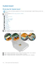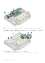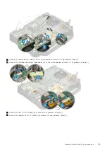
2. Install the two epoxy cap screws on the serial port of the system board [1].
3.
NOTE:
When installing the System Board, technicians must ensure that both the battery cables (1st & 2nd Battery) and
FPC cables (Left I/O FPC and Express Card reader FPC) are not pinched under the System Board.
Install the USB Type-C bracket [2] and secure it with two 'M2.5*5' screws and two 'M1.6*3.0' screws on the system board
[3].
4. Connect the EDP cable [1] and install the EDP bracket on the system board [2].
5. Install the two 'M2*3' screws [3] on the EDP bracket and connect the DC-In cable to the system board [4].
148
Removing and installing components
Содержание Latitude 5424 Rugged
Страница 19: ...130W Technology and components 19 ...
Страница 20: ...LED and Cable 20 Technology and components ...


