background image


Removing the Display Panel 


1.

Follow the instructions in "

Before Working Inside Your Computer

."  


2.

Remove the 

display assembly

.  


3.

Remove the 

display bezel

.  


4.

Remove the M2 x 3-mm ground screw that attaches the display-panel ground wire to the back display cover.  


5.

Remove the eight M2 x 3-mm screws (four on each side of the display panel).  


6.

Lift the display panel out of the display cover.  


7.

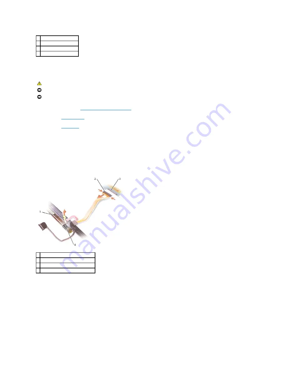
Press in both sides of the top flex-cable connector, and pull the top flex-cable connector away from the display connector.  


8.

Use the pull-tab to disconnect the bottom flex-cable connector from the inverter connector.  


Replacing the Display Panel 


1.

Reconnect the top display cable connector to the top flex-cable connector.  


2.

Reconnect the bottom flex-cable connector to the inverter connector.  


3.

Replace the display panel inside the top cover.  


4.

Replace the M2 x 3-mm ground screw that attaches the display-panel ground wire to the back display cover.  


5.

Replace the eight M2 x 3 screws (four on each side) around the display panel.  
 

1  display grounding screw 

2  display 

3  M2 x 3-mm screws (8) 

4  display back cover 


CAUTION: 

Before you begin the following procedure, see the safety instructions in the 

Product Information Guide

.


NOTICE: 

To avoid electrostatic discharge, ground yourself by using a wrist grounding strap or by touching an unpainted metal surface on the computer.


NOTICE: 

To avoid damaging the system board, you must remove the main battery before you begin working inside the computer. 

1  pull-tab on bottom flex-cable connector 

2  top flex-cable connector  

3  display connector 

4  inverter connector 

Содержание Inspiron XPS

Страница 1: ...a Dell n Series computer any references in this document to Microsoft Windows operating systems are not applicable Information in this document is subject to change without notice 2005 Dell Inc All rights reserved Reproduction in any manner whatsoever without the written permission of Dell Inc is strictly forbidden Trademarks used in this text Dell the DELL logo and Inspiron are trademarks of Dell...

Страница 2: ...d lifting out the bay 8 Remove the screw in the battery latch assembly When you remove the screw the battery latch release on the bottom of the computer will also be removed CAUTION Before you begin any of the procedures in this section follow the safety instructions located in the Product Information Guide NOTICE To avoid electrostatic discharge ground yourself by using a wrist grounding strap or...

Страница 3: ...spring over the hook on the bottom panel using a small screw driver or plastic scribe 3 Place the battery latch release under the bottom panel of the computer and line it up with the hole in the panel then replace the screw in the assembly Ensure that the newly installed latch moves smoothly and freely when pushed and released 4 Replace the hard drive bay and reinsert the three M2 x 3 mm screws 5 ...

Страница 4: ...nside Your Computer Use the following safety guidelines to help protect your computer from potential damage and to help ensure your own personal safety 1 Ensure that the work surface is flat and clean to prevent the computer cover from being scratched 2 Turn off your computer NOTICE To avoid losing data save and close any open files and exit any open programs before you turn off your computer CAUT...

Страница 5: ...r and remove the battery from the bay 7 Turn the computer top side up 8 Remove any installed PC Cards from the PC Card slot Computer Orientation Screw Identification When you are removing and replacing components print Screw Identification as a tool to lay out and keep track of the screws The placemat provides the NOTICE To avoid damaging the system board you must remove the main battery before yo...

Страница 6: ...el 8 each Display Ground Screw 1 each Display Assembly 4 each Display Bezel 4 each under display bumpers 4 each shoulder type under screw covers Modem 1 each USB Port Board 1 each Hard Drive Bay 3 each Palm Rest 7 each top side 11 each bottom side PC Card Reader Cage 4 each Speakers 4 total 2 per speaker ...

Страница 7: ...Back to Contents Page Optical Drive 1 each System Board 4 each Door to Card with Bluetooth Wireless Technology 1 each ...

Страница 8: ...ss F2 during POST to enter the system setup program 4 Press Alt and f to reset the computer defaults 5 Press Esc select Save Exit and press Enter to save configuration changes 6 Remove the flash BIOS update program CD from the drive and restart the computer Back to Contents Page NOTICE Plug the AC adapter into a known good power source to prevent a loss of power Failure to do so may cause system d...

Страница 9: ...rtment 2 Replace the card cover and the screw 3 Replace the battery Back to Contents Page CAUTION Before you begin the following procedure see the safety instructions in the Product Information Guide NOTICE To avoid electrostatic discharge ground yourself by using a wrist grounding strap or by periodically touching an unpainted metal surface such as the back panel on the computer NOTICE To avoid d...

Страница 10: ...elease latch with the positive side up and then push the battery into place b Connect the battery cable to the connector on the system board 2 Replace the keyboard 3 Replace the center control cover CAUTION Before you begin the following procedure see the safety instructions in the Product Information Guide NOTICE To avoid electrostatic discharge ground yourself by using a wrist grounding strap or...

Страница 11: ...Back to Contents Page ...

Страница 12: ...ted metal surface such as the back panel on the computer NOTICE Do not touch the processor die Press and hold the microprocessor down on the substrate on which the die is mounted while turning the cam screw to prevent intermittent contact between the cam screw and microprocessor NOTICE To avoid damage to the microprocessor hold the screwdriver so that it is perpendicular to the microprocessor when...

Страница 13: ...th step 6 Back to Contents Page NOTE The ZIF socket cam screw secures the microprocessor to the system board Take note of the arrow on the ZIF socket cam screw which indicates the direction to turn the cam screw NOTICE Ensure that the cam lock is in the fully open position before seating the microprocessor module Seating the microprocessor module properly in the ZIF socket does not require force N...

Страница 14: ...ION Before you begin the following procedure see the safety instructions in the Product Information Guide NOTICE To avoid electrostatic discharge ground yourself by using a wrist grounding strap or by periodically touching an unpainted metal surface such as the back panel on the computer NOTICE To avoid damaging the system board you must remove the main battery before you begin working inside the ...

Страница 15: ...b to disconnect the LED cable and then disengage the LED cable from the cable channel 9 Remove the four M2 5 x 5 mm screws two on each side that connect the display to the computer base 1 antenna cables 1 display cable pull tab 2 M2 5 x 5 mm screws 4 3 Mini PCI card antenna cables 2 4 display cable connector on system board 1 LED cable 2 Mini PCI card antenna cables NOTE When removing the display ...

Страница 16: ...through the hole in the base of the computer 3 Replace the four M2 5 x 5 mm screws 4 Connect the LED cable to the system board 5 Connect the display cable to the system board 6 Replace the center control cover 7 If a Mini PCI card is installed connect the antenna cables to the card If one is not installed tuck the antenna cables to their secured location 8 Replace the Mini PCI card cover Display B...

Страница 17: ...Then pull the bezel toward the right side of the display assembly to clear the tab on the side B of the lower right corner 1 M2 5 x 5 mm screws 4 2 screw covers 2 3 rubber display bumpers 6 4 shoulder screws 2 CAUTION Before you begin the following procedure see the safety instructions in the Product Information Guide NOTICE To avoid electrostatic discharge ground yourself by using a wrist groundi...

Страница 18: ... Display Bezel 1 Starting at any corner use your fingers to gently snap the bezel into place to secure it to the display panel 2 Replace the four M2 5 x 5 mm screws on the front of the bezel 3 Replace the four shoulder screws and two screw covers 4 Replace the six screw cover display bumpers around the display assembly Display Panel 1 tabs 1 display bezel 2 display panel ...

Страница 19: ...x cable connector 2 Reconnect the bottom flex cable connector to the inverter connector 3 Replace the display panel inside the top cover 4 Replace the M2 x 3 mm ground screw that attaches the display panel ground wire to the back display cover 5 Replace the eight M2 x 3 screws four on each side around the display panel 1 display grounding screw 2 display 3 M2 x 3 mm screws 8 4 display back cover C...

Страница 20: ...ches the latch to the display panel 2 Align the latch with the display panel and slide the latch to the left to secure it into place Back to Contents Page CAUTION Before you begin the following procedure see the safety instructions in the Product Information Guide NOTICE To avoid electrostatic discharge ground yourself by using a wrist grounding strap or by touching an unpainted metal surface on t...

Страница 21: ...he computer CAUTION Before you begin the following procedure see the safety instructions in the Product Information Guide NOTICE To avoid electrostatic discharge ground yourself by using a wrist grounding strap or by periodically touching an unpainted metal surface such as the back panel on the computer NOTICE To avoid damaging the system board you must remove the main battery before you begin wor...

Страница 22: ...s respective screw holes on the system board 2 Replace the four M2 5 x 5 mm screws two on each fan 3 Connect the cables for each fan to the system board Back to Contents Page 1 fan 2 M2 5 x 5 mm screws 2 3 LED system board connector 4 fan system board connector ...

Страница 23: ...bracket and lifting out the bay 8 Remove the screw in the battery latch assembly When you remove the screw the battery latch release on the bottom of the computer will also be removed CAUTION Before you begin any of the procedures in this section follow the safety instructions located in the Product Information Guide NOTICE To avoid electrostatic discharge ground yourself by using a wrist groundin...

Страница 24: ...ng over the hook on the bottom panel using a small screw driver or plastic scribe 3 Place the battery latch release under the bottom panel of the computer and line it up with the hole in the panel then replace the screw in the assembly Ensure that the newly installed latch moves smoothly and freely when pushed and released 4 Replace the hard drive bay and reinsert the three M2 x 3 mm screws 5 Repl...

Страница 25: ......

Страница 26: ...nside Your Computer Use the following safety guidelines to help protect your computer from potential damage and to help ensure your own personal safety 1 Ensure that the work surface is flat and clean to prevent the computer cover from being scratched 2 Turn off your computer NOTICE To avoid losing data save and close any open files and exit any open programs before you turn off your computer CAUT...

Страница 27: ...r and remove the battery from the bay 7 Turn the computer top side up 8 Remove any installed PC Cards from the PC Card slot Computer Orientation Screw Identification When you are removing and replacing components print Screw Identification as a tool to lay out and keep track of the screws The placemat provides the NOTICE To avoid damaging the system board you must remove the main battery before yo...

Страница 28: ...el 8 each Display Ground Screw 1 each Display Assembly 4 each Display Bezel 4 each under display bumpers 4 each shoulder type under screw covers Modem 1 each USB Port Board 1 each Hard Drive Bay 3 each Palm Rest 7 each top side 11 each bottom side PC Card Reader Cage 4 each Speakers 4 total 2 per speaker ...

Страница 29: ...Back to Contents Page Optical Drive 1 each System Board 4 each Door to Card with Bluetooth Wireless Technology 1 each ...

Страница 30: ...ss F2 during POST to enter the system setup program 4 Press Alt and f to reset the computer defaults 5 Press Esc select Save Exit and press Enter to save configuration changes 6 Remove the flash BIOS update program CD from the drive and restart the computer Back to Contents Page NOTICE Plug the AC adapter into a known good power source to prevent a loss of power Failure to do so may cause system d...

Страница 31: ...rtment 2 Replace the card cover and the screw 3 Replace the battery Back to Contents Page CAUTION Before you begin the following procedure see the safety instructions in the Product Information Guide NOTICE To avoid electrostatic discharge ground yourself by using a wrist grounding strap or by periodically touching an unpainted metal surface such as the back panel on the computer NOTICE To avoid d...

Страница 32: ...elease latch with the positive side up and then push the battery into place b Connect the battery cable to the connector on the system board 2 Replace the keyboard 3 Replace the center control cover CAUTION Before you begin the following procedure see the safety instructions in the Product Information Guide NOTICE To avoid electrostatic discharge ground yourself by using a wrist grounding strap or...

Страница 33: ...Back to Contents Page ...

Страница 34: ...ted metal surface such as the back panel on the computer NOTICE Do not touch the processor die Press and hold the microprocessor down on the substrate on which the die is mounted while turning the cam screw to prevent intermittent contact between the cam screw and microprocessor NOTICE To avoid damage to the microprocessor hold the screwdriver so that it is perpendicular to the microprocessor when...

Страница 35: ...th step 6 Back to Contents Page NOTE The ZIF socket cam screw secures the microprocessor to the system board Take note of the arrow on the ZIF socket cam screw which indicates the direction to turn the cam screw NOTICE Ensure that the cam lock is in the fully open position before seating the microprocessor module Seating the microprocessor module properly in the ZIF socket does not require force N...

Страница 36: ...ION Before you begin the following procedure see the safety instructions in the Product Information Guide NOTICE To avoid electrostatic discharge ground yourself by using a wrist grounding strap or by periodically touching an unpainted metal surface such as the back panel on the computer NOTICE To avoid damaging the system board you must remove the main battery before you begin working inside the ...

Страница 37: ...b to disconnect the LED cable and then disengage the LED cable from the cable channel 9 Remove the four M2 5 x 5 mm screws two on each side that connect the display to the computer base 1 antenna cables 1 display cable pull tab 2 M2 5 x 5 mm screws 4 3 Mini PCI card antenna cables 2 4 display cable connector on system board 1 LED cable 2 Mini PCI card antenna cables NOTE When removing the display ...

Страница 38: ...through the hole in the base of the computer 3 Replace the four M2 5 x 5 mm screws 4 Connect the LED cable to the system board 5 Connect the display cable to the system board 6 Replace the center control cover 7 If a Mini PCI card is installed connect the antenna cables to the card If one is not installed tuck the antenna cables to their secured location 8 Replace the Mini PCI card cover Display B...

Страница 39: ...Then pull the bezel toward the right side of the display assembly to clear the tab on the side B of the lower right corner 1 M2 5 x 5 mm screws 4 2 screw covers 2 3 rubber display bumpers 6 4 shoulder screws 2 CAUTION Before you begin the following procedure see the safety instructions in the Product Information Guide NOTICE To avoid electrostatic discharge ground yourself by using a wrist groundi...

Страница 40: ... Display Bezel 1 Starting at any corner use your fingers to gently snap the bezel into place to secure it to the display panel 2 Replace the four M2 5 x 5 mm screws on the front of the bezel 3 Replace the four shoulder screws and two screw covers 4 Replace the six screw cover display bumpers around the display assembly Display Panel 1 tabs 1 display bezel 2 display panel ...

Страница 41: ...x cable connector 2 Reconnect the bottom flex cable connector to the inverter connector 3 Replace the display panel inside the top cover 4 Replace the M2 x 3 mm ground screw that attaches the display panel ground wire to the back display cover 5 Replace the eight M2 x 3 screws four on each side around the display panel 1 display grounding screw 2 display 3 M2 x 3 mm screws 8 4 display back cover C...

Страница 42: ...ches the latch to the display panel 2 Align the latch with the display panel and slide the latch to the left to secure it into place Back to Contents Page CAUTION Before you begin the following procedure see the safety instructions in the Product Information Guide NOTICE To avoid electrostatic discharge ground yourself by using a wrist grounding strap or by touching an unpainted metal surface on t...

Страница 43: ...he computer CAUTION Before you begin the following procedure see the safety instructions in the Product Information Guide NOTICE To avoid electrostatic discharge ground yourself by using a wrist grounding strap or by periodically touching an unpainted metal surface such as the back panel on the computer NOTICE To avoid damaging the system board you must remove the main battery before you begin wor...

Страница 44: ...ts respective screw holes on the system board 2 Replace the four M2 5 x 5 mm screws two on each fan 3 Connect the cables for each fan to the system board Back to Contents Page 1 fan 2 M2 5 x 5 mm screws 2 3 LEDsystem board connector 4 fan system board connector ...

Страница 45: ...AUTION Before you begin the following procedure see the safety instructions in the Product Information Guide NOTICE To avoid damaging the system board you must remove the main battery before you begin working inside the computer NOTICE To prevent data loss turn off your computer before removing the hard drive Do not remove the hard drive while the computer is on in standby mode or in hibernate mod...

Страница 46: ...ing a Hard Drive to Dell Return your old hard drive to Dell in its original or comparable foam packaging Otherwise the hard drive may be damaged in transit Back to Contents Page 1 hard drive 2 foam packaging ...

Страница 47: ... to left Replacing the Center Control Cover Gently snap the cover back in place starting from left to right Back to Contents Page CAUTION Before you begin any of the procedures in this section follow the safety instructions located in the Product Information Guide NOTICE To avoid electrostatic discharge ground yourself by using a wrist grounding strap or by periodically touching an unpainted metal...

Страница 48: ...safety instructions in the Product Information Guide NOTICE To avoid electrostatic discharge ground yourself by using a wrist grounding strap or by periodically touching an unpainted metal surface such as the back panel on the computer NOTICE To avoid damaging the system board you must remove the main battery before you begin working inside the computer NOTICE The key caps on the keyboard are frag...

Страница 49: ... keyboard into the computer base 3 Replace the two M2 5 x 5 mm screws across the top of the keyboard 4 Replace the center control cover Back to Contents Page display panel NOTE You may need to push the bottom of the keyboard down slightly to seat the keyboard into the computer base ...

Страница 50: ...er replaceable parts of the computer To replace an LED set you must replace the part that holds the LED set Front LEDs The front LEDs are integrated into the system speakers To replace the front LEDs see Replacing the Speakers Top LEDs The top LEDs are integrated into the display cover To replace the top LEDs you must replace the display cover which is removed during the display panel removal proc...

Страница 51: ... mm screws that secure the MCH heat sink to the system board Replacing the MCH Heat Sink 1 Place the MCH heat sink over the screw holes on the system board 2 Replace the screw s that secure the MCH heat sink to the system board Back to Contents Page CAUTION Before you perform the following procedures see the safety instructions in the Product Information Guide NOTICE To avoid electrostatic dischar...

Страница 52: ......

Страница 53: ...tions in the Product Information Guide NOTICE To prevent static damage to components inside your computer discharge static electricity from your body before you touch any of your computer s electronic components You can do so by touching an unpainted metal surface NOTE Memory modules purchased from Dell are covered under your computer warranty NOTE To get maximum performance dual channel memory ba...

Страница 54: ... or connect the AC adapter to your computer and an electrical outlet 4 Turn on the computer As the computer boots it detects the additional memory and automatically updates the system configuration information Back to Contents Page NOTE To get maximum performance dual channel memory bandwidth capability both memory module connectors must contain memory modules and the modules must be of the same s...

Страница 55: ...structions noted below Only products approved for use in your portable computer may be installed Approved Mini PCI cards may be purchased only from Dell CAUTION Before you begin any of the procedures in this section follow the safety instructions located in the Product Information Guide NOTICE To avoid damaging the system board you must remove the main battery before you begin working inside the c...

Страница 56: ... card into the connector until it clicks 2 Connect the antenna cables to the Mini PCI card NOTICE To prevent damage to the Mini PCI card connector do not use tools to spread the securing clips that secure the card 1 Mini PCI card 2 metal securing tabs 2 NOTICE To avoid damaging the antenna cables or the Mini PCI card never place the cables under the card NOTICE The connectors are keyed to ensure c...

Страница 57: ...3 Replace the cover Back to Contents Page 1 antenna cables 2 ...

Страница 58: ...e pull tab to disconnect the modem from the connector on the system board CAUTION Before you begin any of the procedures in this section follow the safety instructions located in the Product Information Guide NOTICE To avoid electrostatic discharge ground yourself by using a wrist grounding strap or by periodically touching an unpainted metal surface such as the back panel on the computer NOTICE T...

Страница 59: ...oard Align the connector on the bottom of the modem with the modem connector on the system board and press down on the right side of the modem 3 Replace the M2 x 3 mm screw Back to Contents Page NOTICE Do not disconnect the modem cable from the system board NOTICE Ensure that the modem cable is routed correctly when you replace the modem ...

Страница 60: ...rt a screwdriver into the indentation and push the notch on the metal tab to release the drive from the bay 4 Pull the device out of the drive bay Replacing the Optical Drive 1 Slide the optical drive into the drive bay and snap it into place 2 Replace the M2 5 x 8 mm screw that secures the drive in place Back to Contents Page NOTICE To prevent damage to drives store them in a safe dry place when ...

Страница 61: ...gin the following procedure see the safety instructions in the Product Information Guide NOTICE To avoid electrostatic discharge ground yourself by using a wrist grounding strap or by periodically touching an unpainted metal surface such as the back panel on the computer NOTICE To avoid damaging the system board you must remove the main battery before you begin working inside the computer NOTE The...

Страница 62: ...st with the bottom plastics and gently snap into place 2 Reconnect the touch pad connector to the system board 3 Reconnect the LED board to the system board 4 Replace the coin cell battery 5 Replace the seven M2 5 x 5 mm screws on the top side of the palm rest 6 Turn the computer over and replace the eleven M2 5 x 8 mm screws on the bottom of the computer 7 Replace the Internal Card With Bluetooth...

Страница 63: ...8 Replace the display assembly 9 Replace the keyboard 10 Replace the center control cover Back to Contents Page ...

Страница 64: ...m board 9 Remove the four M2 x 3 mm screws that attach the PC Card reader cage to the top of the hard drive bay Back to Contents Page CAUTION Before you begin the following procedure see the safety instructions in the Product Information Guide NOTICE To avoid electrostatic discharge ground yourself by using a wrist grounding strap or by periodically touching an unpainted metal surface such as the ...

Страница 65: ...ctor S Video TV Out Connector IEEE 1394 Connector USB Connector Video Connector S Video TV Out Connector Pin Signal 1 USB5V 2 USBP 3 USBP 4 GND Pin Signal Pin Signal 1 CRT_R 9 5V 2 CRT_G 10 GND 3 CRT_B 11 MONITOR_DETECT 4 NC 12 DDC_DATA 5 GND 13 CRT_HS 6 GND 14 CRT_VS 7 GND 15 DDC_CLK 8 GND S Video Pin Signal 1 GND ...

Страница 66: ...IEEE 1394 Connector Back to Contents Page 2 GND 3 DLUMA L 4 DCRMA L Composite Video Pin Signal 5 NC 6 DCMPS L 7 GND Pin Signal 1 TPB 2 TPB 3 TPA 4 TPA ...

Страница 67: ...odule s 5 Remove the Mini PCI card 6 Remove the modem 7 Remove the center control cover 8 Remove the keyboard 9 Remove the display assembly 10 Turn the computer over and disconnect the modem cable from the system board connector 11 Disconnect the modem cable from the modem 12 Remove the palm rest CAUTION Before you begin the following procedure see the safety instructions in the Product Informatio...

Страница 68: ...wireless technology from the system board 20 Disconnect the subwoofer connector from the system board 21 Disconnect the USB connector from the system board 22 Disconnect both fan connectors and both fan LED connectors from the system board 23 Disconnect the PC Card connector from the system board 1 PC Card connector 2 M2 5 x 5 mm stiffener bracket screw 3 stiffener bracket 4 PC Card connector on s...

Страница 69: ...r right corner of the system board and slide it toward the right to remove the system board from the computer base Replacing the System Board 1 Perform all of the steps in Removing the System Board in reverse order 2 Turn on the computer 3 Insert the flash BIOS update program CD that accompanied the replacement system board into the optical drive Follow the instructions that appear on the screen 2...

Страница 70: ...4 Enter the system setup program to update the BIOS on the new system board with the computer Service Tag sequence Back to Contents Page ...

Страница 71: ...ctors to the system board connectors 2 Gently align the speakers on the screw holes for securing the speakers to the computer base 3 Replace the four M2 5 x 5 mm screws to secure the speakers in place two on each speaker CAUTION Before you begin any of the procedures in this section follow the safety instructions located in the Product Information Guide NOTICE To avoid electrostatic discharge grou...

Страница 72: ...4 Re route the speaker cables into the cable guides and re adhere the tape to secure the speaker cables in place on the computer base Back to Contents Page ...

Страница 73: ...h procedure in this document assumes that a part can be replaced by performing the removal procedure in reverse order 1 display assembly 12 speakers 2 center control cover 13 subwoofer 3 palm rest with touch pad 14 optical drive 4 mini PCI card 15 system board 5 fan 16 fan 6 video card thermal cooling assembly 17 microprocessor 7 computer base 18 microprocessor thermal cooling assembly 8 hard driv...

Страница 74: ...thermal cooling assembly and remove it from the system board Replacing the Microprocessor Thermal Cooling Assembly 1 Evenly apply thermal grease to the top surface of the microprocessor 2 Place the microprocessor thermal cooling assembly over the microprocessor 3 Tighten the four captive screws labeled 1 through 4 in consecutive order CAUTION Before you begin the following procedure see the safety...

Страница 75: ...Back to Contents Page ...

Страница 76: ...lp If you purchased a Dell n Series computer any references in this document to Microsoft Windows operating systems are not applicable Model PP14L February 2005 Rev A00 Back to Contents Page NOTE A NOTE indicates important information that helps you make better use of your computer NOTICE A NOTICE indicates either potential damage to hardware or loss of data and tells you how to avoid the problem ...

Страница 77: ...tom panel at the back of the board and over the pin on the front side of the board 2 Reinstall the M2 5 x 5 mm screw securing the board 3 Insert the connector into the system board 4 Perform the steps to Remove the USB port board in reverse CAUTION Before you begin any of the procedures in this section follow the safety instructions located in the Product Information Guide NOTICE To avoid electros...

Страница 78: ... the palm rest 6 Replace the display assembly 7 Replace the keyboard 8 Replace the center control cover 9 Replace the battery and other items removed in Before Working Inside Your Computer Back to Contents Page ...

Страница 79: ... Thermal Cooling Assembly 1 Carefully re align the video card thermal cooling assembly over the connector on the system board and press down CAUTION Before performing the following procedures read the safety instructions in your Product Information Guide NOTICE To avoid electrostatic discharge ground yourself by using a wrist grounding strap or by periodically touching an unpainted metal surface s...

Страница 80: ...2 Tighten the four captive screws on the video card thermal cooling assembly Back to Contents Page ...

Страница 81: ...aptive screws that secure the subwoofer in place 8 Remove the subwoofer cable connector from the system board Replacing the Subwoofer 1 Reconnect the subwoofer cable to the system board 2 Place the subwoofer onto the system board 3 Tighten the two captive screws that secure the subwoofer in place CAUTION Before performing the following procedures read the safety instructions in your Product Inform...

Страница 82: ...Back to Contents Page ...

Страница 83: ...AUTION Before you begin the following procedure see the safety instructions in the Product Information Guide NOTICE To avoid damaging the system board you must remove the main battery before you begin working inside the computer NOTICE To prevent data loss turn off your computer before removing the hard drive Do not remove the hard drive while the computer is on in standby mode or in hibernate mod...

Страница 84: ...ing a Hard Drive to Dell Return your old hard drive to Dell in its original or comparable foam packaging Otherwise the hard drive may be damaged in transit Back to Contents Page 1 hard drive 2 foam packaging ...

Страница 85: ... to left Replacing the Center Control Cover Gently snap the cover back in place starting from left to right Back to Contents Page CAUTION Before you begin any of the procedures in this section follow the safety instructions located in the Product Information Guide NOTICE To avoid electrostatic discharge ground yourself by using a wrist grounding strap or by periodically touching an unpainted metal...

Страница 86: ...safety instructions in the Product Information Guide NOTICE To avoid electrostatic discharge ground yourself by using a wrist grounding strap or by periodically touching an unpainted metal surface such as the back panel on the computer NOTICE To avoid damaging the system board you must remove the main battery before you begin working inside the computer NOTICE The key caps on the keyboard are frag...

Страница 87: ... keyboard into the computer base 3 Replace the two M2 5 x 5 mm screws across the top of the keyboard 4 Replace the center control cover Back to Contents Page display panel NOTE You may need to push the bottom of the keyboard down slightly to seat the keyboard into the computer base ...

Страница 88: ...er replaceable parts of the computer To replace an LED set you must replace the part that holds the LED set Front LEDs The front LEDs are integrated into the system speakers To replace the front LEDs see Replacing the Speakers Top LEDs The top LEDs are integrated into the display cover To replace the top LEDs you must replace the display cover which is removed during the display panel removal proc...

Страница 89: ... mm screws that secure the MCH heat sink to the system board Replacing the MCH Heat Sink 1 Place the MCH heat sink over the screw holes on the system board 2 Replace the screw s that secure the MCH heat sink to the system board Back to Contents Page CAUTION Before you perform the following procedures see the safety instructions in the Product Information Guide NOTICE To avoid electrostatic dischar...

Страница 90: ......

Страница 91: ...tions in the Product Information Guide NOTICE To prevent static damage to components inside your computer discharge static electricity from your body before you touch any of your computer s electronic components You can do so by touching an unpainted metal surface NOTE Memory modules purchased from Dell are covered under your computer warranty NOTE To get maximum performance dual channel memory ba...

Страница 92: ... or connect the AC adapter to your computer and an electrical outlet 4 Turn on the computer As the computer boots it detects the additional memory and automatically updates the system configuration information Back to Contents Page NOTE To get maximum performance dual channel memory bandwidth capability both memory module connectors must contain memory modules and the modules must be of the same s...

Страница 93: ...structions noted below Only products approved for use in your portable computer may be installed Approved Mini PCI cards may be purchased only from Dell CAUTION Before you begin any of the procedures in this section follow the safety instructions located in the Product Information Guide NOTICE To avoid damaging the system board you must remove the main battery before you begin working inside the c...

Страница 94: ... card into the connector until it clicks 2 Connect the antenna cables to the Mini PCI card NOTICE To prevent damage to the Mini PCI card connector do not use tools to spread the securing clips that secure the card 1 Mini PCI card 2 metal securing tabs 2 NOTICE To avoid damaging the antenna cables or the Mini PCI card never place the cables under the card NOTICE The connectors are keyed to ensure c...

Страница 95: ...3 Replace the cover Back to Contents Page 1 antenna cables 2 ...

Страница 96: ...e pull tab to disconnect the modem from the connector on the system board CAUTION Before you begin any of the procedures in this section follow the safety instructions located in the Product Information Guide NOTICE To avoid electrostatic discharge ground yourself by using a wrist grounding strap or by periodically touching an unpainted metal surface such as the back panel on the computer NOTICE T...

Страница 97: ...oard Align the connector on the bottom of the modem with the modem connector on the system board and press down on the right side of the modem 3 Replace the M2 x 3 mm screw Back to Contents Page NOTICE Do not disconnect the modem cable from the system board NOTICE Ensure that the modem cable is routed correctly when you replace the modem ...

Страница 98: ...rt a screwdriver into the indentation and push the notch on the metal tab to release the drive from the bay 4 Pull the device out of the drive bay Replacing the Optical Drive 1 Slide the optical drive into the drive bay and snap it into place 2 Replace the M2 5 x 8 mm screw that secures the drive in place Back to Contents Page NOTICE To prevent damage to drives store them in a safe dry place when ...

Страница 99: ...gin the following procedure see the safety instructions in the Product Information Guide NOTICE To avoid electrostatic discharge ground yourself by using a wrist grounding strap or by periodically touching an unpainted metal surface such as the back panel on the computer NOTICE To avoid damaging the system board you must remove the main battery before you begin working inside the computer NOTE The...

Страница 100: ...st with the bottom plastics and gently snap into place 2 Reconnect the touch pad connector to the system board 3 Reconnect the LED board to the system board 4 Replace the coin cell battery 5 Replace the seven M2 5 x 5 mm screws on the top side of the palm rest 6 Turn the computer over and replace the eleven M2 5 x 8 mm screws on the bottom of the computer 7 Replace the Internal Card With Bluetooth...

Страница 101: ...8 Replace the display assembly 9 Replace the keyboard 10 Replace the center control cover Back to Contents Page ...

Страница 102: ...m board 9 Remove the four M2 x 3 mm screws that attach the PC Card reader cage to the top of the hard drive bay Back to Contents Page CAUTION Before you begin the following procedure see the safety instructions in the Product Information Guide NOTICE To avoid electrostatic discharge ground yourself by using a wrist grounding strap or by periodically touching an unpainted metal surface such as the ...

Страница 103: ...ctor S Video TV Out Connector IEEE 1394 Connector USB Connector Video Connector S Video TV Out Connector Pin Signal 1 USB5V 2 USBP 3 USBP 4 GND Pin Signal Pin Signal 1 CRT_R 9 5V 2 CRT_G 10 GND 3 CRT_B 11 MONITOR_DETECT 4 NC 12 DDC_DATA 5 GND 13 CRT_HS 6 GND 14 CRT_VS 7 GND 15 DDC_CLK 8 GND S Video Pin Signal 1 GND ...

Страница 104: ...IEEE 1394 Connector Back to Contents Page 2 GND 3 DLUMA L 4 DCRMA L Composite Video Pin Signal 5 NC 6 DCMPS L 7 GND Pin Signal 1 TPB 2 TPB 3 TPA 4 TPA ...

Страница 105: ...ctors to the system board connectors 2 Gently align the speakers on the screw holes for securing the speakers to the computer base 3 Replace the four M2 5 x 5 mm screws to secure the speakers in place two on each speaker CAUTION Before you begin any of the procedures in this section follow the safety instructions located in the Product Information Guide NOTICE To avoid electrostatic discharge grou...

Страница 106: ...4 Re route the speaker cables into the cable guides and re adhere the tape to secure the speaker cables in place on the computer base Back to Contents Page ...

Страница 107: ...em 7 Remove the center control cover 8 Remove the keyboard 9 Remove the display assembly 10 Turn the computer over and disconnect the modem cable from the system board connector 11 Disconnect the modem cable from the modem 12 Remove the palm rest 13 Remove the M2 x 3 mm screw that holds the stiffener bracket next to the hard drive cage and remove the stiffener bracket CAUTION Before you begin the ...

Страница 108: ...fer connector from the system board 21 Disconnect the USB connector from the system board 22 Disconnect both fan connectors and both fan LED connectors from the system board 23 Disconnect the PC Card connector from the system board 1 PC Card connector 2 stiffener bracket screw 3 stiffener bracket 4 PC Card connector on system board NOTE Remove the video card thermal cooling assembly as a single un...

Страница 109: ... toward the right to remove the system board from the computer base Replacing the System Board 1 Perform all of the steps in Removing the System Board in reverse order 2 Turn on the computer 3 Insert the flash BIOS update program CD that accompanied the replacement system board into the optical drive Follow the instructions that appear on the screen 4 Enter the system setup program to update the B...

Страница 110: ...Back to Contents Page ...

Страница 111: ...h procedure in this document assumes that a part can be replaced by performing the removal procedure in reverse order 1 display assembly 12 speakers 2 center control cover 13 subwoofer 3 palm rest with touch pad 14 optical drive 4 mini PCI card 15 system board 5 fan 16 fan 6 video card thermal cooling assembly 17 microprocessor 7 computer base 18 microprocessor thermal cooling assembly 8 hard driv...

Страница 112: ...thermal cooling assembly and remove it from the system board Replacing the Microprocessor Thermal Cooling Assembly 1 Evenly apply thermal grease to the top surface of the microprocessor 2 Place the microprocessor thermal cooling assembly over the microprocessor 3 Tighten the four captive screws labeled 1 through 4 in consecutive order CAUTION Before you begin the following procedure see the safety...

Страница 113: ...Back to Contents Page ...

Страница 114: ...rks used in this text Dell the DELL logo and Inspiron are trademarks of Dell Inc Microsoft and Windows are registered trademarks of Microsoft Corporation Bluetooth is a trademark owned by Bluetooth SIG Inc and is used by Dell Inc under license Other trademarks and trade names may be used in this document to refer to either the entities claiming the marks and names or their products Dell Inc discla...

Страница 115: ...tom panel at the back of the board and over the pin on the front side of the board 2 Reinstall the M2 5 x 5 mm screw securing the board 3 Insert the connector into the system board 4 Perform the steps to Remove the USB port board in reverse CAUTION Before you begin any of the procedures in this section follow the safety instructions located in the Product Information Guide NOTICE To avoid electros...

Страница 116: ... the palm rest 6 Replace the display assembly 7 Replace the keyboard 8 Replace the center control cover 9 Replace the battery and other items removed in Before Working Inside Your Computer Back to Contents Page ...

Страница 117: ... Thermal Cooling Assembly 1 Carefully re align the video card thermal cooling assembly over the connector on the system board and press down CAUTION Before performing the following procedures read the safety instructions in your Product Information Guide NOTICE To avoid electrostatic discharge ground yourself by using a wrist grounding strap or by periodically touching an unpainted metal surface s...

Страница 118: ...2 Tighten the four captive screws on the video card thermal cooling assembly Back to Contents Page ...

Страница 119: ...aptive screws that secure the subwoofer in place 8 Remove the subwoofer cable connector from the system board Replacing the Subwoofer 1 Reconnect the subwoofer cable to the system board 2 Place the subwoofer onto the system board 3 Tighten the two captive screws that secure the subwoofer in place CAUTION Before performing the following procedures read the safety instructions in your Product Inform...

Страница 120: ...Back to Contents Page ...

Отзывы: