


Overview................................................................................................................................................................................5
Features................................................................................................................................................................................. 5
Packing list............................................................................................................................................................................ 5
Optional accessories........................................................................................................................................................... 6
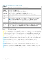
EGW-5200 system specifications....................................................................................................................................7
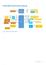
EGW-5200 system block diagram................................................................................................................................... 9
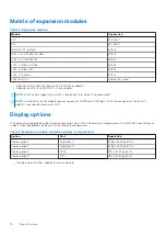
Matrix of expansion modules.......................................................................................................................................... 10
Display options....................................................................................................................................................................10
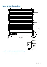
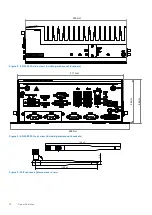
Mechanical dimensions......................................................................................................................................................11
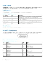
Power button................................................................................................................................................................ 14
LED indicators............................................................................................................................................................... 14
Reset button..................................................................................................................................................................14
DisplayPort connectors...............................................................................................................................................14
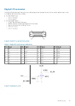
Digital I/O connector...................................................................................................................................................15
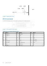
DVI-D connector...........................................................................................................................................................16
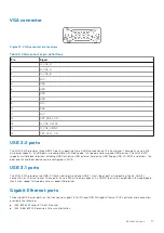
VGA connector..............................................................................................................................................................17
USB 2.0 ports................................................................................................................................................................17
USB 3.1 ports.................................................................................................................................................................17
Gigabit Ethernet ports................................................................................................................................................ 17
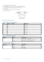
DC power input.............................................................................................................................................................19
COM port connectors................................................................................................................................................. 19
Remote power button connector............................................................................................................................ 20
Mainboard connector locations................................................................................................................................ 21
USB 2.0 connector......................................................................................................................................................22
Mini PCIe connector................................................................................................................................................... 22
SATA connector...........................................................................................................................................................22
Clear CMOS jumper.................................................................................................................................................... 23
Extended PWR/RESET header................................................................................................................................23
USIM slot....................................................................................................................................................................... 23
Attach the WiFi antennas................................................................................................................................................25
Attach DC power connector.......................................................................................................................................... 26
Power on and start up the operating system............................................................................................................. 27
Mount the device.............................................................................................................................................................. 27
Expansion module installation.........................................................................................................................................28
Contents
Contents
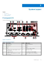
3
Содержание EGW-5200
Страница 1: ...Dell EMC Edge Gateway 5200 User s Guide January 2022 Rev A01 ...
Страница 21: ...Internal I O connectors Mainboard connector locations Figure 17 Mainboard connectors System Layout 21 ...
Страница 31: ...Main Figure 27 BIOS screen Main tab BIOS Setup 31 ...
Страница 32: ...Advanced Figure 28 BIOS screen Advanced tab 32 BIOS Setup ...
Страница 33: ...CPU Configuration Figure 29 CPU Configuration top of screen BIOS Setup 33 ...
Страница 47: ...NVMe Configuration Figure 41 NVMe Configuration BIOS Setup 47 ...
Страница 51: ...Memory Configuration Figure 45 Memory Configuration BIOS Setup 51 ...
Страница 54: ...PCH IO Configuration Figure 48 PCH IO Configuration 54 BIOS Setup ...
Страница 56: ...Security Configuration Figure 50 Security Configuration 56 BIOS Setup ...
Страница 57: ...M 2 Device Configuration Figure 51 M 2 Device Configuration BIOS Setup 57 ...
Страница 58: ...Security Figure 52 BIOS screen Security tab 58 BIOS Setup ...
Страница 64: ...Save and Exit Figure 57 BIOS screen Save and Exit tab 64 BIOS Setup ...
Страница 65: ...Event logs Figure 58 BIOS screen Event logs tab BIOS Setup 65 ...