Attach DC power connector
Prerequisites
CAUTION:
Before providing DC power, ensure the voltage and polarity provided are compatible with the DC
input. Improper input voltage and/or polarity can be responsible for system damage.
Steps
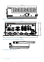
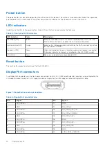
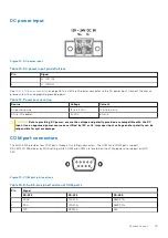
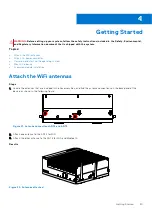
1. Locate the DC power connector that is included in the Accessory Box, as shown in the following figure.
Figure 23. DC power connector
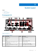
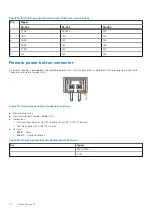
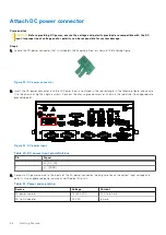
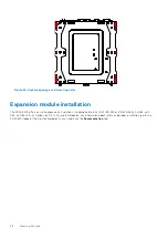
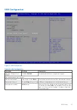
2. Insert the DC power connector into the DC Power Input, as outlined in the red rectangle in the following figure, and secure
it to the chassis using the captive screws. Connect the chassis ground screw, as shown in the red circle, to an appropriate
grounding point.
Figure 24. DC power input
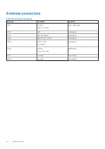
Table 20. DC power input pin definitions
Pin
Signal
1
V+ (DC_IN)
2
V– (DGND)
3. Connect a DC power source to the inputs of the DC power connector, making sure to use the correct input voltage and
polarity. Use an approved power source as certified by IEC or UL.
Table 21. Power source rating
Source
Voltage
Current
DC power source
12 to 24 VDC
12 A to 6 A min.
AC-to-DC adapter
24 VDC
6 A min.
26
Getting Started
Содержание EGW-5200
Страница 1: ...Dell EMC Edge Gateway 5200 User s Guide January 2022 Rev A01 ...
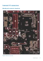
Страница 21: ...Internal I O connectors Mainboard connector locations Figure 17 Mainboard connectors System Layout 21 ...
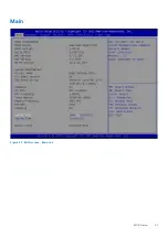
Страница 31: ...Main Figure 27 BIOS screen Main tab BIOS Setup 31 ...
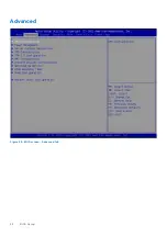
Страница 32: ...Advanced Figure 28 BIOS screen Advanced tab 32 BIOS Setup ...
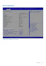
Страница 33: ...CPU Configuration Figure 29 CPU Configuration top of screen BIOS Setup 33 ...
Страница 47: ...NVMe Configuration Figure 41 NVMe Configuration BIOS Setup 47 ...
Страница 51: ...Memory Configuration Figure 45 Memory Configuration BIOS Setup 51 ...
Страница 54: ...PCH IO Configuration Figure 48 PCH IO Configuration 54 BIOS Setup ...
Страница 56: ...Security Configuration Figure 50 Security Configuration 56 BIOS Setup ...
Страница 57: ...M 2 Device Configuration Figure 51 M 2 Device Configuration BIOS Setup 57 ...
Страница 58: ...Security Figure 52 BIOS screen Security tab 58 BIOS Setup ...
Страница 64: ...Save and Exit Figure 57 BIOS screen Save and Exit tab 64 BIOS Setup ...
Страница 65: ...Event logs Figure 58 BIOS screen Event logs tab BIOS Setup 65 ...