
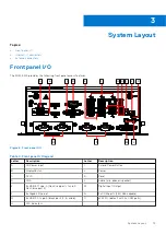
Power button
The power button is a non-latched push button with a blue LED indicator. The system is turned on when the button is pressed,
and the power LED is illuminated. If the system hangs, press the button for five seconds to turn off the system.
LED indicators
In addition to the LED of the power button, three LEDs on the front panel indicate the following.
Table 5. Front panel LED indicators
LED indicator
Color
Description
Watchdog (WD)
Yellow
Indicates watchdog timer status. When watchdog timer starts, the LED
flashes. When the timer is expired, the LED remains illuminated.
Hard disk drive (HD)
Orange
Indicates the storage operating state. When the SATA hard drive is active,
the LED indicator flashes.
Diagnostic (DG)
Green
When illuminated continuously, indicates no physical storage is connected.
If blinking, indicates no memory is installed on either SO-DIMM socket.
U1/U2/U3
Green
Behavior can be adjusted using onboard GPIO.
Reset button
The reset button executes a hard reset for the EGW-5200.
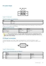
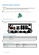
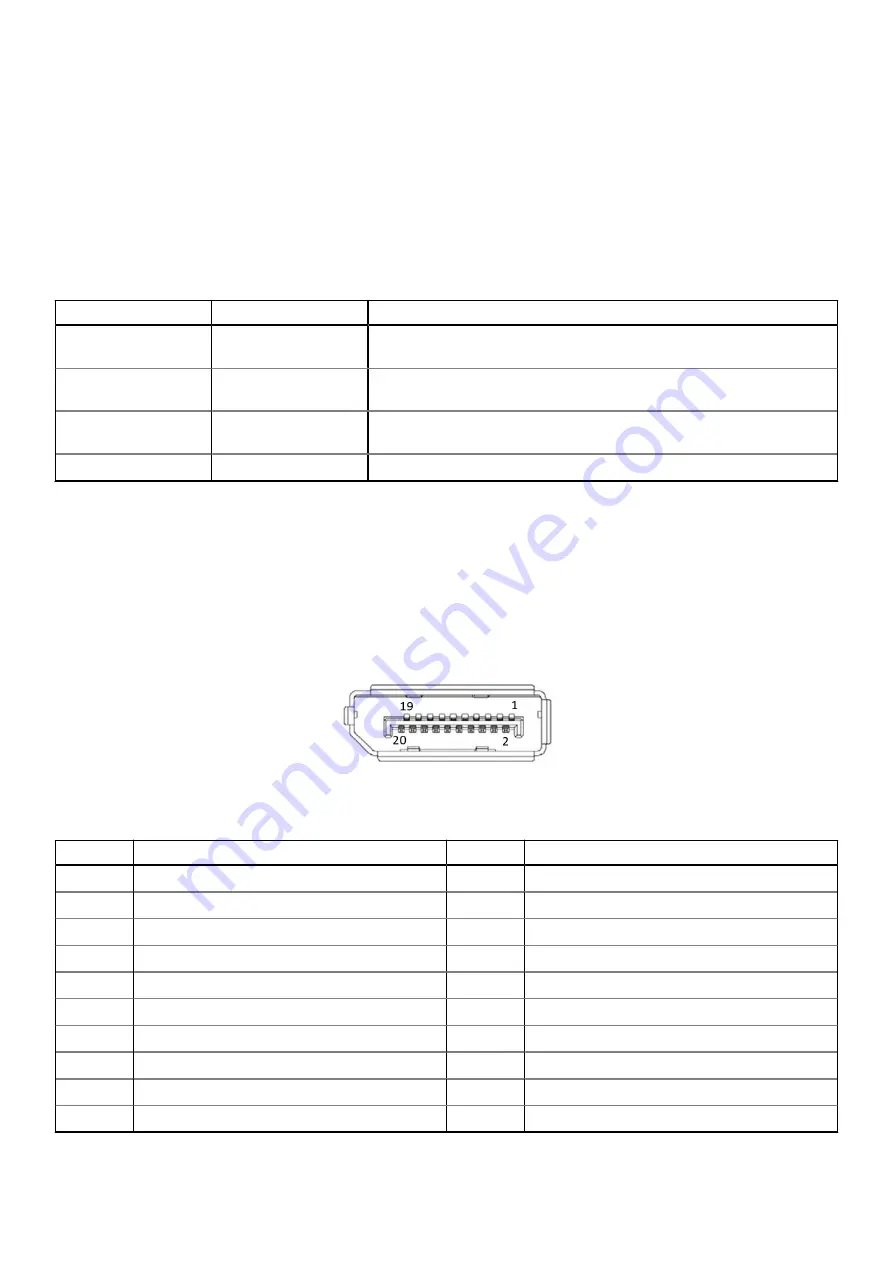
DisplayPort connectors
Two DisplayPort connectors on the front panel can connect to VGA, DVI, HDMI, and DisplayPort monitors using a DisplayPort to
VGA adapter cable, DisplayPort to DVI adapter cable, or DisplayPort to HDMI adapter cable and DisplayPort cable.
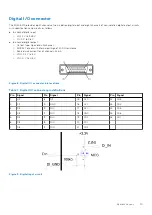
Figure 7. DisplayPort connector pin locations
Table 6. DisplayPort pin definitions
Pin
Signal
Pin
Signal
1
C
11
GND
2
GND
12
CN_DDPx3–
3
CN_DDPx0–
13
CN_DDPx_AUX_SEL
4
C
14
CN_DDPx_CONFIG2
5
GND
15
CN_D
6
CN_DDPx1–
16
GND
7
C
17
CN_DDPx_AUX–
8
GND
18
CN_DDPx_HPD
9
CN_DDPx2–
19
GND
10
C
20
+V3.3_DDPx_PWR_CN
14
System Layout
Содержание EGW-5200
Страница 1: ...Dell EMC Edge Gateway 5200 User s Guide January 2022 Rev A01 ...
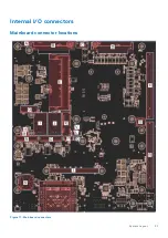
Страница 21: ...Internal I O connectors Mainboard connector locations Figure 17 Mainboard connectors System Layout 21 ...
Страница 31: ...Main Figure 27 BIOS screen Main tab BIOS Setup 31 ...
Страница 32: ...Advanced Figure 28 BIOS screen Advanced tab 32 BIOS Setup ...
Страница 33: ...CPU Configuration Figure 29 CPU Configuration top of screen BIOS Setup 33 ...
Страница 47: ...NVMe Configuration Figure 41 NVMe Configuration BIOS Setup 47 ...
Страница 51: ...Memory Configuration Figure 45 Memory Configuration BIOS Setup 51 ...
Страница 54: ...PCH IO Configuration Figure 48 PCH IO Configuration 54 BIOS Setup ...
Страница 56: ...Security Configuration Figure 50 Security Configuration 56 BIOS Setup ...
Страница 57: ...M 2 Device Configuration Figure 51 M 2 Device Configuration BIOS Setup 57 ...
Страница 58: ...Security Figure 52 BIOS screen Security tab 58 BIOS Setup ...
Страница 64: ...Save and Exit Figure 57 BIOS screen Save and Exit tab 64 BIOS Setup ...
Страница 65: ...Event logs Figure 58 BIOS screen Event logs tab BIOS Setup 65 ...