

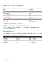
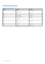
Matrix of expansion modules
Table 2. Expansion modules
Module
Connection
4G
M.2 2280
5G
a
M.2 2280
WiFi AX210
- default
mPCIe
uFM - 2x COM RS-422/485
mPCIe
uFM - 2x COM RS-232
mPCIe
uFM - 2x GbE with PoE
mPCIe
uFM - 2x GbE LAN
mPCIe
uFM - 2x Canbus
mPCIe
uFM - 8x DI/O
Internal I2C wafer
a.
Requires an M.2 2280 B+M key to M.2 3042 B-key adapter.
b.
Requires an mPCIE to M.2 2230 A+E key adapter.
NOTE:
uFM can only support one unit at a time due to the shared I/O panel bracket.
NOTE:
Installation of a uFM module requires removal of COM3 and COM4 ports. With the exception of the 8x DI/O
module, it also requires removal of WiFi.
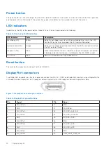
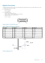
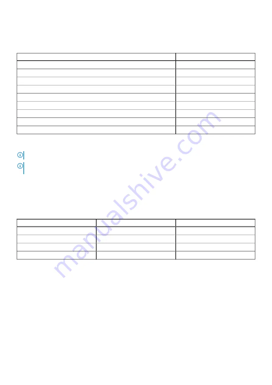
Display options
With computing and graphic performance enhancement from its 9th Generation Intel processors, the EGW-5200 controller can
support three independent displays with the following configurations.
Table 3. Maximum available resolution display configurations
Option
Port
Resolution
Display option 1
DisplayPort1
4096 x 2304 @ 60 Hz
Display option 2
DisplayPort2
4096 x 2304 @ 60 Hz
Display option 3
DVI-D
1920 x 1200 @ 60 Hz
Display option 4
VGA
1920 x 1080 @ 60 Hz
a.
Disabled when all other video ports are connected.
10
Specifications
Содержание EGW-5200
Страница 1: ...Dell EMC Edge Gateway 5200 User s Guide January 2022 Rev A01 ...
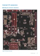
Страница 21: ...Internal I O connectors Mainboard connector locations Figure 17 Mainboard connectors System Layout 21 ...
Страница 31: ...Main Figure 27 BIOS screen Main tab BIOS Setup 31 ...
Страница 32: ...Advanced Figure 28 BIOS screen Advanced tab 32 BIOS Setup ...
Страница 33: ...CPU Configuration Figure 29 CPU Configuration top of screen BIOS Setup 33 ...
Страница 47: ...NVMe Configuration Figure 41 NVMe Configuration BIOS Setup 47 ...
Страница 51: ...Memory Configuration Figure 45 Memory Configuration BIOS Setup 51 ...
Страница 54: ...PCH IO Configuration Figure 48 PCH IO Configuration 54 BIOS Setup ...
Страница 56: ...Security Configuration Figure 50 Security Configuration 56 BIOS Setup ...
Страница 57: ...M 2 Device Configuration Figure 51 M 2 Device Configuration BIOS Setup 57 ...
Страница 58: ...Security Figure 52 BIOS screen Security tab 58 BIOS Setup ...
Страница 64: ...Save and Exit Figure 57 BIOS screen Save and Exit tab 64 BIOS Setup ...
Страница 65: ...Event logs Figure 58 BIOS screen Event logs tab BIOS Setup 65 ...