Diagnostics information
2-15
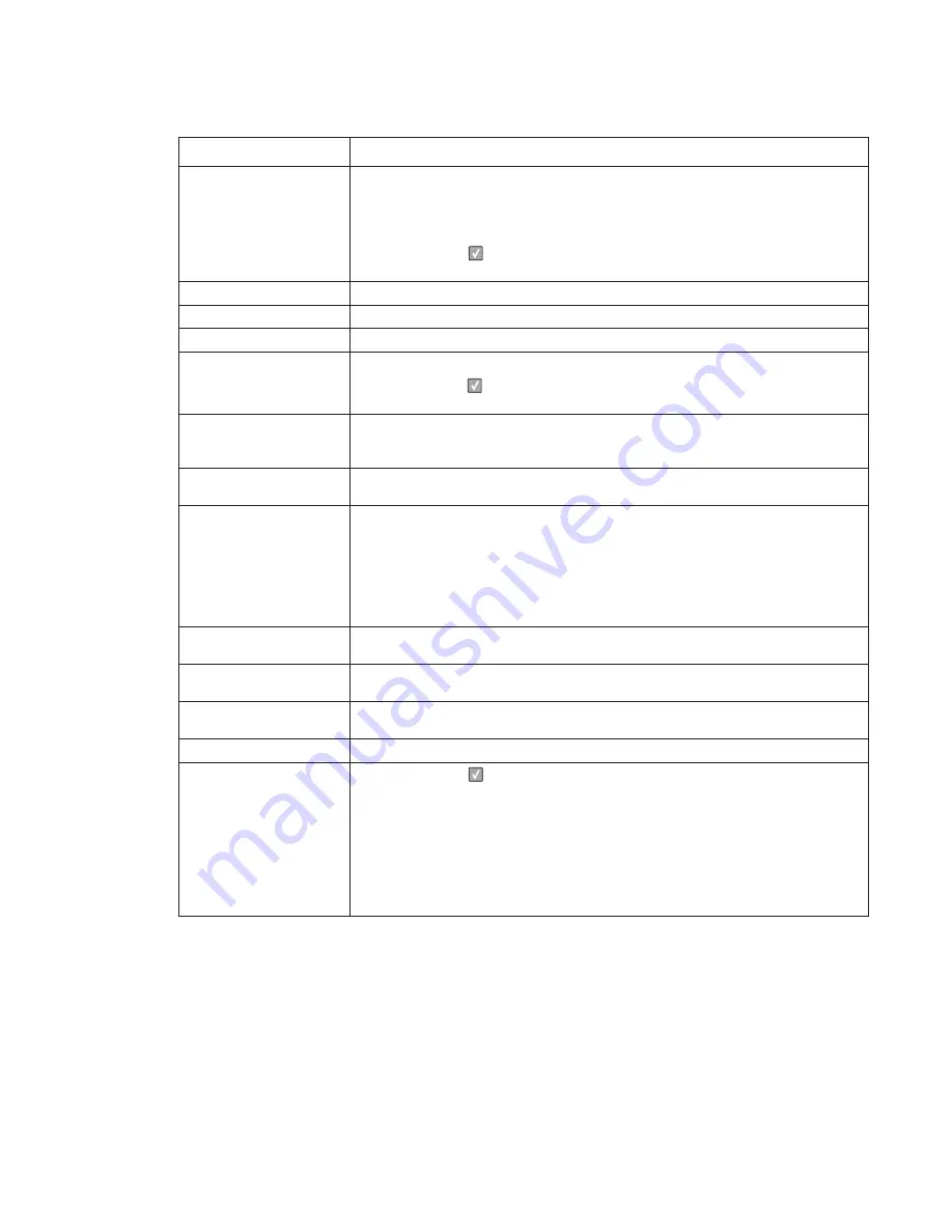
Load Manual
<
type
> <
size
>
Printer does not detect media meeting the description <
type
> and <
size
> in the
single sheet feeder (manual feeder).
The following actions can be taken:
• Load paper and the job continues.
• press
Select
(
), and choose an alternate source for media.
• Cancel the current job.
Paper Changes Needed
Change or load new media.
PJL OP Message
PJL Seed Message
PJL ST Message
Try one or more of the following:
• press
Select
(
) to clear the message, and continue printing.
• Wait for the message to clear.
Remove Paper ADF
This posts when there is paper detected in the ADF upon POR or when the cover
is closed (or any other situation that re-inits the scanner). Message clears when
paper is removed.
Remove Paper
Standard Bin
The standard output bin is full or nearly full. Remove the media from the bin.
Restore Held Jobs. Go/
Stop?
Held jobs were found on disk after a power on/off reset. Restoring will make these
jobs available. Jobs may also be restored at a later time by turning off and
restarting the printer.
The following actions can be taken:
• Restore
• Do not restore
• More information
Securely Clearing Disk
Space
This message appears when all blocks of the disk are cleared.
Unsupported USB
Device, Please Remove
Remove the unrecognized device from the USB port on the front of the printer.
Unsupported USB Hub,
please remove
Remove the unrecognized USB hub/device from the USB port on the front of the
printer.
Unsupported Disk
Remove the unsupported disk before continuing.
34 Short Paper
• press
Select
(
)
to clear the message and continue printing.
The printer does not automatically reprint the page that prompted the
message.
• Check tray length and width guides to ensure paper is properly fitted in the tray.
• Make sure the print job is requesting the correct size of paper.
• Adjust the Paper Size setting for the size paper you are using.
If MP Feeder Size is set to Universal, make sure the paper is large enough for
the formatted data.
• Cancel the current job.
User status and attendance messages (Continued)
User primary message
Explanation
Содержание 3333DN
Страница 1: ... 02 Nov 2009 ...
Страница 2: ... ...
Страница 10: ...x Service Manual ...
Страница 15: ...Notices and safety information xv ...
Страница 16: ...xvi Service Manual ...
Страница 28: ...1 8 Service Manual ...
Страница 31: ...General information 1 11 Reduce Enlarge 25 to 400 Copy only ...
Страница 151: ...Diagnostic aids 3 47 3 Remove the jam 4 Close the rear door 5 Close the front door 6 Touch Continue ...
Страница 157: ...Diagnostic aids 3 53 4 Remove the ADF separator roll 5 Remove the jammed media 6 Reinstall the ADF separator roll ...
Страница 160: ...3 56 Service Manual ...
Страница 172: ...4 12 2 Remove the three screws B securing the top of the controller shield B ...
Страница 180: ...4 20 5 Lift the duplex slightly push to the left and tilt to clear the right side of the printer 6 Remove the duplex ...
Страница 182: ...4 22 6 Remove the screw D from the gear E 7 Remove the plastic bushing F ...
Страница 183: ...Repair information 4 23 8 Use a screwdriver to pop the retainer clip G loose from the gear 9 Remove the gear H ...
Страница 186: ...4 26 6 Disconnect the MPF from the lower front cover 7 Disconnect the fuser link A from the front access door A ...
Страница 192: ...4 32 2 Carefully pull the scanner front cover away from the tub assembly ...
Страница 205: ...Repair information 4 45 5 Remove the three screws B from the left door mount B ...
Страница 208: ...4 48 8 Use a screwdriver to pop the inner shaft lock B loose 9 Remove the inner shaft lock C ...
Страница 211: ...Repair information 4 51 5 Remove the e clip B 6 Remove the media feed clutch with cable C ...
Страница 217: ...Repair information 4 57 7 Open the front access door and remove the lower paper guide B ...
Страница 219: ...Repair information 4 59 5 Remove the three screws B from the left side of the printer B ...
Страница 250: ...4 90 12 Disconnect LSU HSYNC extension cable at the connector in the middle of the cable ...
Страница 251: ...Repair information 4 91 13 Remove the three screws A from the left rear frame assembly A A A ...
Страница 252: ...4 92 14 Remove the three screws B from the right rear frame assembly B B B ...
Страница 272: ...4 112 6 Insert the fax card interface cable into the system board connector 7 Lower and lock the scanner assembly ...
Страница 282: ...6 2 Service Manual ...
Страница 284: ...7 2 Service Manual Assembly 1 Covers 3 11 7 13 5 16 9 15 2 10 6 17 4 12 8 14 1 17 18 ...
Страница 286: ...7 4 Service Manual Assembly 2 Imaging 3 11 7 13 5 16 9 15 2 10 6 4 12 8 14 1 ...
Страница 288: ...7 6 Service Manual Assembly 3 Tray assemblies 3 2 1 5 4 ...
Страница 290: ...7 8 Service Manual Assembly 4 Electronics 11 12 7 13 6 14 8 1 2 3 4 5 9 10 17 20 18 19 22 21 16 15 ...
Страница 292: ...7 10 Service Manual Assembly 5 Frame 7 1 2 5 6 7 12 8 See instruction sheet in the FRU 9 10 11 3 4 3 ...
Страница 296: ...7 14 Service Manual ...
Страница 304: ...I 8 Service Manual ...


