2-68
Service Manual
Escalating a fax issue to second-level support
Before contacting the second-level support, go to the SE menu on the MFP.and generate a Fax error file. This
file contains machine settings information and debug information that will help second-level support determine
the cause of a failure.
To generate the fax error file, perform the following steps:
1.
In a Web browser, type http://MFP ip address/se.
2.
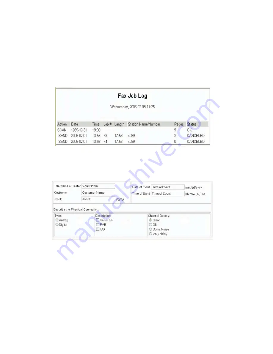
The MFP’s SE menu page will display. Click the “Dump Job History” link. The following displays:
3.
Write down the type of connection, the type of error, and the job in which the error occurred.
4.
In the Web browser address bar, type http://MFP ipaddress/se.
5.
Click
Report a Fax Problem
(A). The fax check list displays.
6.
Fill in the requested information. This is where you will type in the information you retrieved in step 3.
Second-level support can assist you if you have questions about the information requested on the page.
Note:
The fields requesting the code levels, model number, type of problem are auto-filled. If the information is
not in the fields, it can be retrieved from the SE menu. The SE menu can be accessed by pressing **411 on the
keypad or typing http://MFP ipaddress/se in a Web browser.
7.
After all the requested information is entered into the Fax Checklist Web page, press the
Submit
button on
the bottom of the page. A dialogue asking you to save the file will appear.
Note:
The file generated by the MFP is not automatically transmitted to second-level support. It is placed
on the computer desktop.
8.
Enter a name for the file, and indicate where you want to save the file.
9.
press
OK
. The file appears on the desktop.
10.
E-mail the file to second-level support.
Содержание 3333DN
Страница 1: ... 02 Nov 2009 ...
Страница 2: ... ...
Страница 10: ...x Service Manual ...
Страница 15: ...Notices and safety information xv ...
Страница 16: ...xvi Service Manual ...
Страница 28: ...1 8 Service Manual ...
Страница 31: ...General information 1 11 Reduce Enlarge 25 to 400 Copy only ...
Страница 151: ...Diagnostic aids 3 47 3 Remove the jam 4 Close the rear door 5 Close the front door 6 Touch Continue ...
Страница 157: ...Diagnostic aids 3 53 4 Remove the ADF separator roll 5 Remove the jammed media 6 Reinstall the ADF separator roll ...
Страница 160: ...3 56 Service Manual ...
Страница 172: ...4 12 2 Remove the three screws B securing the top of the controller shield B ...
Страница 180: ...4 20 5 Lift the duplex slightly push to the left and tilt to clear the right side of the printer 6 Remove the duplex ...
Страница 182: ...4 22 6 Remove the screw D from the gear E 7 Remove the plastic bushing F ...
Страница 183: ...Repair information 4 23 8 Use a screwdriver to pop the retainer clip G loose from the gear 9 Remove the gear H ...
Страница 186: ...4 26 6 Disconnect the MPF from the lower front cover 7 Disconnect the fuser link A from the front access door A ...
Страница 192: ...4 32 2 Carefully pull the scanner front cover away from the tub assembly ...
Страница 205: ...Repair information 4 45 5 Remove the three screws B from the left door mount B ...
Страница 208: ...4 48 8 Use a screwdriver to pop the inner shaft lock B loose 9 Remove the inner shaft lock C ...
Страница 211: ...Repair information 4 51 5 Remove the e clip B 6 Remove the media feed clutch with cable C ...
Страница 217: ...Repair information 4 57 7 Open the front access door and remove the lower paper guide B ...
Страница 219: ...Repair information 4 59 5 Remove the three screws B from the left side of the printer B ...
Страница 250: ...4 90 12 Disconnect LSU HSYNC extension cable at the connector in the middle of the cable ...
Страница 251: ...Repair information 4 91 13 Remove the three screws A from the left rear frame assembly A A A ...
Страница 252: ...4 92 14 Remove the three screws B from the right rear frame assembly B B B ...
Страница 272: ...4 112 6 Insert the fax card interface cable into the system board connector 7 Lower and lock the scanner assembly ...
Страница 282: ...6 2 Service Manual ...
Страница 284: ...7 2 Service Manual Assembly 1 Covers 3 11 7 13 5 16 9 15 2 10 6 17 4 12 8 14 1 17 18 ...
Страница 286: ...7 4 Service Manual Assembly 2 Imaging 3 11 7 13 5 16 9 15 2 10 6 4 12 8 14 1 ...
Страница 288: ...7 6 Service Manual Assembly 3 Tray assemblies 3 2 1 5 4 ...
Страница 290: ...7 8 Service Manual Assembly 4 Electronics 11 12 7 13 6 14 8 1 2 3 4 5 9 10 17 20 18 19 22 21 16 15 ...
Страница 292: ...7 10 Service Manual Assembly 5 Frame 7 1 2 5 6 7 12 8 See instruction sheet in the FRU 9 10 11 3 4 3 ...
Страница 296: ...7 14 Service Manual ...
Страница 304: ...I 8 Service Manual ...


