Viper User
Manual (001-5008-000 Rev6)
Page
50
Radio Capabilities
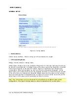
Tx & Rx Frequency Range and Output Power Range is factory set.
140-5018-500/501: VHF, 136.000-174.000 MHz, 1-10W
140-5048-300/301: UHF Range 3, 406.125-470.000 MHz, 1-10W
140-5048-500/501: UHF Range 5, 450.000-511.975 MHz, 1-10W
140-5098-500/501: 900, 928.000-960.000 MHz, 1-8W
Current Radio Settings
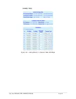
Displays the current Rx & Tx Frequencies, Output Power, and Channel Type programmed
into the radio.
Channels
Transmitter Disabled radio button is set at the factory to disable the radio until a valid
frequency has been entered. The radio will not transmit until a valid frequency has been
entered and the transmitter has been enabled.
There are 32 channels available in the Viper. The radio button beside each channel will
select that channel as the active channel. Each channel can operate in simplex (one
frequency) or half duplex (pair of frequencies) mode. The transmit power output level can
be set for each channel. The channel type can be selected for each channel. All Vipers in a
network must be set to the same channel type.
Note: It is the installer’s responsibility to check the FCC license to determine the correct
parameters and settings for channel frequencies, power level, and channel type.
SERIAL PORTS SETUP
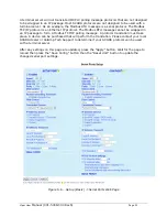
The Viper has two serial ports. Either port can be configured to send data over the air,
connect to the CLI (command line interface), report online diagnostics, or be custom
configured to send/receive data on a specific port to/from a specific IP address.
By default the Setup port is configured to connect to the CLI at 19200 baud. The Com port
is configured to send data in DOX mode at 9600 baud. By default the Com port will send
data as a UDP multicast message to all the other Vipers on the network (10.255.255.255)
on port 6278. When DOX mode is selected on the Setup port, the Setup port will send data
as a UDP multicast message to all the other Vipers on the network on port 6277. If other
configurations are needed, the Viper allows for custom configuration of the transport
protocol, IP Addresses, and ports the Setup port and Com port will connect with.
The serial custom configuration will allow the user to program the serial port as a terminal
server. A terminal server will translate the serial protocol to an Internet Protocol (IP). A
terminal server will wrap serial data presented at the serial port in an IP package (IP header
and associated checksums). When an IP message is sent to the terminal server’s
corresponding IP address, the IP package is stripped off.

