background image


Viper User

 Manual (001-5008-000 Rev6)


Page 

22


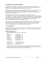
Min Safety Distance 
(VHF @ max power) 

123cm 218.8cm  389cm 

Min Safety Distance 
(UHF @ max power) 

105.7cm 188cm  334.4cm 

Min Safety Distance 
(900 MHz @ max power) 

63.8cm 

115 cm 

201.7 cm 


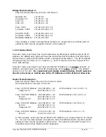
Note:  It is the responsibility of the user to guarantee compliance with the FCC 

MPE regulations when operating this device in a way other than described above.


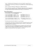
The Viper radio uses a low power radio frequency transmitter. The concentrated energy 

from an antenna may pose a health hazard. People should not be in front 

of the antenna when the transmitter is operating. 


The installer of this equipment must ensure the antenna is located or pointed such that it 

does not emit an RF field in excess of Health Canada limits for the general population. 
Recommended safety guidelines for the human exposure to radio frequency electromagnetic 

energy are contained in the Canadian Safety Code 6 (available from Health Canada) and the 
Federal Communications Commission (FCC) Bulletin 65. 

 
Any changes or modifications not expressly approved by the party responsible for 

compliance (in the country where used) could void the user's authority to operate the 
equipment. 

TERRAIN AND SIGNAL STRENGTH 

A line of sight path between stations is highly desirable and provides the most reliable 
communications link in all cases.  A line of sight path can often be achieved by mounting 

each station antenna on a tower or other elevated structure that raises it high enough to 
clear surrounding terrain and other obstructions.  

 
The requirement for a clear transmission path depends on the distance to be covered by the 

system.  If the system is to cover a limited distance, say 3-5 miles, then some obstructions 
in the transmission path may be tolerable.  For longer-range systems, any obstruction could 
compromise the performance of the system, or block transmission entirely.  

 
The signal strength (RSSI) at the receiver must exceed the receiver sensitivity by an 

amount known as the fade margin to provide reliable operation under various conditions.  
Fade margin (expressed in dB) is the maximum tolerable reduction in received signal 

strength, which still provides an acceptable signal quality.  This compensates for reduced 
signal strength due to multi-path, slight antenna movement or changing atmospheric 

losses.  CalAmp recommends a 30 dB fade margin for most projects.  Table 2.3 shows the 
RSSI versus Reliability. 

RF Exposure 

Содержание 140-5018-500

Страница 1: ...Viper 100 Viper 400 Viper 900 Narrowband IP Router User Manual PN 001 5008 000 Rev 6 Revised December 2009 ...

Страница 2: ...ded information about TCP Proxy Feature Added note to RF Acknowledgment section Corrected Viper Power Cable Part in Accessory Table Added specifications and part number for 900 MHz Viper Updated RF Exposure Compliance requirements Added section 2 10 Choosing an IP Addressing Scheme 5 July 2009 Added information about V1 6 Viper code release Added information about Listen Before Transmit Disable fe...
Страница 3: ...r unit must be professionally installed and must ensure a minimum separation distance listed in the table below between the radiating structure and any person An antenna mounted on a pole or tower is the typical installation and in rare instances a 1 2 wave whip antenna is used Antenna Gain 5 dBi 10 dBi 15 dBi Min Safety Distance VHF max Power 123cm 218 8cm 389cm Min Safety Distance UHF max Power ...

Страница 4: ... Point to Point 17 2 3 1 Point to Multipoint 18 2 3 2 Report by Exception 18 2 4 Extending the Coverage Area with a Relay Point 18 2 4 1 Understanding RF Path Requirements 19 2 5 Site Selection and Site Survey 19 2 5 1 Site Selection 19 2 5 2 Site Survey 20 2 6 Selecting Antenna and Feedline 20 2 6 1 Antenna Gain 20 2 6 2 Omni Directional Antenna 20 2 6 3 Yagi Antenna 20 2 6 4 Vertical Dipoles 21 ...

Страница 5: ...ettings 46 6 2 1 Ethernet Interface 46 6 2 2 RF Interface 47 6 2 3 Default Gateway 48 6 3 Channel Table 48 6 4 Serial Ports Setup 50 6 4 1 Basic Settings 52 6 4 2 IP Gateway Service 52 6 4 3 IP Gateway Transport 53 6 4 4 RTS CTS Mode Settings 57 7 SETUP ADVANCED 58 7 1 RF Optimizations 58 7 1 1 MAC Advanced Settings 58 7 1 2 Carrier Sense Level Threshold 59 7 1 3 Listen Before Transmit 59 7 2 IP S...

Страница 6: ... 90 10 6 Feature Options 90 11 NEIGHBOR MANAGEMENT 91 11 1 User Interface 91 11 2 Neighbor Discovery Modes 91 11 2 1 Manual SCAN 92 11 2 2 Auto SCAN 92 11 2 3 Disabled 92 11 3 Local Status 92 11 3 1 Neighbor Discovery States 93 11 3 2 Neighboring Vipers Found 94 11 3 3 Discovery Duration 94 11 4 Discovered Viper Neighbors 94 11 4 1 Information on Neighboring Vipers 94 11 4 2 Neighbor Table Entry T...

Страница 7: ...t Rate 100 12 2 3 Increase OIP and MAC Retries Limit 101 13 UPGRADING YOUR FIRMWARE 102 13 1 Software Release History 102 13 2 Upgrade Modem Firmware Procedure 103 13 3 Upgrade Radio Firmware 103 13 4 Verify File Integrity 105 VIPER SPECIFICATIONS 106 PRODUCT WARRANTY 109 DEFINITIONS 111 ...

Страница 8: ...d IEEE 802 3 compliant Viper supports any protocol running over IPv4 including ICMP IPinIP IPSec RSVP TCP and UDP protocols It provides MAC layer bridging and HTTP ARP and static routing packet forwarding OPERATIONAL CHARACTERISTICS The Viper product has the following operational characteristics Frequency range of 136 174 MHz 406 1 470 MHz 450 512 MHz or 928 960 MHz User selectable data rates Buil...

Страница 9: ...ion commissioning maintenance and troubleshooting can be done locally or remotely There are no physical switches or adjustments all operating parameters are set via a web browser The Dual Port Viper provides a receive antenna connector allowing for unique customer applications requiring additional receive filtering external PA s and other options Long Range Narrowband configurations allow better c...

Страница 10: ...Blinking Viper no faults normal operations Viper scanning for neighbors Viper has a fault condition check unit status Viper detects high background noise ACT Blinking Green Off Ethernet activity detected on PHY link RJ45 No Ethernet activity on PHY link RJ45 Lnk Green Off Ethernet connection established RJ45 No Ethernet connection RJ45 Rx Tx Green Red Receiving data Transmitting data 1 1 3 Etherne...

Страница 11: ...M port 9 Contact DE 9 Connector Contact EIA 232F Function Signal Direction 1 DCD 1 DTE DCE 2 RXD DTE DCE 3 TXD DTE DCE 4 DTR DTE DCE 5 GND DTE DCE 6 DSR 2 DTE DCE 7 RTS 1 DTE DCE 8 CTS 1 DTE DCE 9 RING 3 DTE DCE 1 Programmable 2 Always asserted 3 For future use The DCD DTR RTS and CTS control lines are programmable Refer to section 6 4 for serial port control line configurations 1 1 5 Power Connec...

Страница 12: ...dditional receive filtering external PA s and other options Warning The transmit antenna port must not be connected directly to the receive antenna port of the Dual Port Viper Excessive power into the receive antenna port will damage the radio Input power to the receiver should not exceed 17 dBm 50mW To reduce potential interference the antenna type and its gain should be chosen to ensure the effe...

Страница 13: ...ies including antenna feedline and connectors tested and approved for use with the Viper Table 1 6 Accessories ITEM PART NUMBER Viper Power Cable 897 5008 010 Viper Demo Kit VHF 136 174 MHz 250 5018 500 Viper Demo Kit UHF 406 470 MHz 250 5048 300 Viper Demo Kit UHF 450 512 MHz 250 5048 500 Factory Installed Viper Fan Kit 150 5008 001 Field Installed Viper Fan Kit 150 5008 002 TNC Male to N Male 18...

Страница 14: ...ies 18 TNC male to N male jumper cable and weather kit UHF 900 kits include 25 feet of LMR400 antenna feedline Feedline is available for VHF kits in 25 or 50 feet lengths Table 1 8 Feedline and Connectors ITEM PART NUMBER 25 feet antenna feedline LMR400 N Male 250 0200 025 50 feet antenna feedline LMR400 N Male 250 0200 055 Barrel Connector RF1 N type Female 250 0200 100 PRODUCT WARRANTY It is our...

Страница 15: ...ES ON HAND WHEN CALLING For units in warranty customers are responsible for shipping charges to CalAmp Wireless DataCom For units returned out of warranty customers are responsible for all shipping charges Return shipping instructions are the responsibility of the customer DOCUMENTATION AND DOWNLOADS CalAmp reserves the right to update its products software or documentation without obligation to n...

Страница 16: ... Access Point The unit configured as an Access Point would allow access to the Internet but an Access Point is not required in all networks Most SCADA networks have a polling master but the polling master is not necessarily configured any different than the remotes It is the responsibility of the polling master to control RF traffic so RF collisions do not occur Note In a radio system only one rad...

Страница 17: ...lAmp recommends the user program the polling sequence in each protocol with logic that interacts with the other s protocol Done and Error bits The Ethernet polling protocol would not be allowed to send a message until the current Ethernet message is either Done or Error and the previous RS232 message are either Done or Error bits are set The RS232 polling protocol would also have a similar logic P...

Страница 18: ...er most Report by Exception systems have a master remote polling component The master polls the remotes once every hour or half hour to ensure there is still a valid communication path In a Report by Exception configuration there will not be a master controlling RF traffic and RF collisions will often occur The Viper has several collision avoidance features to help minimize collisions The Viper is...

Страница 19: ...measured in dBm A radio modem requires a minimum amount of received RF signal to operate reliably and provide adequate data throughput This is the radio s receiver sensitivity In most cases spectrum regulators will define or limit the amount of signal that can be transmitted and it will be noted on the FCC license This is the effective isotropic radiated power EIRP Transmitted power decays with di...

Страница 20: ...the energy both vertically and horizontally as in the case of the flashlight and Yagi antenna Gain can be also be achieved by reducing the vertical angle of radiation leaving the horizontal alone In this case the antenna will radiate equally in all horizontal directions but will take energy that otherwise would have gone skywards and use it to increase the horizontal radiation The required antenna...

Страница 21: ...F 900 MHz LMR 400 1 5 dB 2 7 dB 3 9 dB 1 2 Heliax 0 68 dB 1 51 dB 2 09 dB 7 8 Heliax 0 37 dB 0 83 dB 1 18 dB 1 5 8 Heliax 0 22 dB 0 51 dB 0 69 dB Outside cable connections should have a weather kit applied to each connection to prevent moisture Feedline connections should be routinely inspected to minimize signal loss through the connection A 3 dB loss in signal strength due to cable loss and or b...

Страница 22: ...ere used could void the user s authority to operate the equipment TERRAIN AND SIGNAL STRENGTH A line of sight path between stations is highly desirable and provides the most reliable communications link in all cases A line of sight path can often be achieved by mounting each station antenna on a tower or other elevated structure that raises it high enough to clear surrounding terrain and other obs...

Страница 23: ...b Directional antennas should be used at the remote end of the link They confine the transmission and reception pattern to a comparatively narrow beam which minimizes interference to and from stations located outside the pattern c If interference is suspected from another system it may be helpful to use antenna polarization opposite to the interfering system s antennas An additional 20 dB or more ...

Страница 24: ...ork support readily available to them and the authorization required to make changes in the network Router mode requires set up of IP Ethernet and Serial IP addresses Figure 2 6 shows a Viper Router Mode configuration Figure 2 6 Viper Router Mode Configuration Viper 192 168 205 1 Viper 192 168 206 1 PLC 192 168 206 2 Viper 192 168 207 1 PLC 192 168 207 2 Viper 192 168 208 1 PLC 192 168 208 2 HMI P...

Страница 25: ...rom 192 168 205 1 to 192 168 205 254 are valid and may be assigned to a host When any host needs to communicate with another device that is not within the same local area network it will first send the data packet to the gateway or router The gateway or router will forward the packet to the desired location Often times a packet will pass through several gateways or routers to get to its final dest...

Страница 26: ...s Ethernet IP Address on a unique network In addition all Vipers must have their RF IP addresses on the same network The default network is 10 0 0 0 8 For consistent and reliable communication the RF network should not overlap or contain any of the IP Addresses in the Ethernet networks Router Mode Example 1 Ethernet Subnet Mask May vary from Viper to Viper RF Subnet Mask for all units 255 0 0 0 Vi...

Страница 27: ...s 10 0 0 1 16 Viper 2 Eth IP Address 10 200 1 17 28 RF IP Address 10 0 0 2 16 Viper 3 Eth IP Address 10 200 1 33 28 RF IP Address 10 0 0 3 16 Viper 4 Eth IP Address 10 200 1 49 28 RF IP Address 10 0 0 4 16 Viper 177 Eth IP Address 10 200 12 1 28 RF IP Address 10 0 0 177 16 Viper 178 Eth IP Address 10 200 12 17 28 RF IP Address 10 0 0 178 16 Each Viper has an Ethernet IP address on a unique network...

Страница 28: ...n in Figure 3 1 to provide stable radio communications between demo devices Figure 3 1 Demo Antenna Assembly Note It is important to use attenuation between all demo units in the test network to reduce the amount of signal strength in the test environment PC LAN SETUP On a PC running MS Windows with an existing LAN connection connect to the Ethernet input of the Viper and complete the steps in sec...

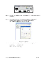
Страница 29: ...ons STEP 2 Right click the Local Area Connection icon to open the Properties box Scroll through the list and highlight Internet Protocol TCP IP Click Properties to open the TCP IP Properties box Figure 3 4 PC LAN Setup STEP 3 Select Use the Following IP Address and enter the following values IP Address 192 168 205 254 Subnet Mask 255 255 255 0 Default Gateway leave empty ...

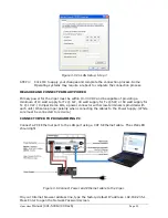
Страница 30: ...1W 40 watt supply for Tx 5W or 60 watt supply for Tx 10 W In Viper Demo Kits a power connector with screw terminals is provided with each unit Observe proper polarity when connecting the cables to the Power Supply White wire must be connected to red wire CONNECT VIPER TO PROGRAMMING PC Connect a PC s Ethernet port to the LAN port using a CAT 5 Ethernet cable The LINK LED should light Figure 3 6 Co...

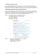
Страница 31: ...b interface Log into the Viper web interface as described in Initial Installation Login Follow the instructions below to configure the Viper using the setup wizard All units are factory programmed with an IP address of 192 168 205 1 Repeat these steps to program additional Viper units STEP 1 Station Name Assign a unique Station Name IP Forwarding Mode Select Bridge Mode Relay Point Select No Acces...

Страница 32: ...0 Rev6 Page 32 Figure 3 8 Using the Setup Wizard Step 2 To monitor or change configuration remotely each unit requires a unique IP Address When configuring more than one unit be sure to increment IP addresses Click Apply Click Next ...

Страница 33: ...xt Figure 3 9 Using the Setup Wizard Step 3 STEP 4 The Viper uses AES 128 bit encryption to protect your data from intrusion Use of encryption is optional but we strongly recommend it for network configuration The encryption phrase key must be common to all units in a network Encryption Disabled Encryption Click Disabled Click Apply Click Next Encryption Enabled Encryption Click Enabled Encryption...

Страница 34: ...will see a green success icon on the bottom left of the page when save is complete Figure 3 11 Using the Setup Wizard Step 5 If you have changed any parameters marked with a yellow icon you must cycle power to the unit using the Reset Unit button Your unit is now functioning in Bridge Mode CHECK FOR NORMAL OPERATION To simulate data traffic over the radio network connect a PC or LAN to the Etherne...

Страница 35: ...e is subdivided in two frames the left frame allows the user to navigate the main menu while the right main frame displays the selected page Figure 4 1 Viper Welcome Screen MAIN MENU VIPER Main menu grants the user access to Unit Status Setup Wizard Basic and Advanced Setup Security Statistics Maintenance and Network Management 1 1 27Network Management System Commands The remaining buttons on the ...

Страница 36: ...parameters into flash memory Failure to use this command button will result in the loss of temporarily entered parameters when the unit is reset Reset Unit Once satisfied all parameters have been applied and saved use the Reset Unit command button to make flash changes permanent When a unit is reset a 20 second station reset timer counts down Status reports Ready when reset is complete ...

Страница 37: ...FAMA UHFVHF PROD Vx y_Rxxx where Product Name Viper Protocol Name Licensed Band s of Operation VHF 136 174 MHz UHF 406 1 512 MHz 900 928 960 MHz Production Build Vx y Rxxx where Vx y is Major minor version number and Rxxx is Sequential Package Release Build Number Station Name Displays the name of the connected unit Configured under Setup Basic D General D Station Name Local Time Displays time zon...

Страница 38: ... Unit Status Displays the status of the Viper and reports any errors If you do not receive the OK indicator EX Error Power On Self Test FAILURE Warning Radio TX Synthesizer lock failure N A use the ACKNOWLEGDE UNIT STATUS and REFRESH buttons to reset the modem If the problem persists contact CalAmp Technical Services for additional information Have the displayed Unit Status message available if co...

Страница 39: ...em Firmware Version Displays the modem firmware version of the unit Radio Firmware Version Displays the radio firmware version of the unit RSSI from RF MAC Displays the Received Signal Strength Indication RSSI from the unit with the MAC address displayed The RSSI displayed range is from approximately 50 dBm to 120 dBm At signal strengths greater than 50 dBm the radio will still operate but will no...

Страница 40: ...in range this line will report normal The Viper radio can be configured to send an SNMP trap if the Reverse Power goes into a fault state Power state Indicates if the unit is running at full power or at a reduced power The TX power will foldback when the temperature is too hot or the Power Amp PA current is too high In extreme cases of high temperature or high current the Viper transmitter will sh...

Страница 41: ...mote units with IPSD enabled IPSD can be enabled disabled under Setup Advanced D IP Services Ver Version of the online diagnostics Different versions may have different parameters This document describes Version 1 Number of items that follow in the online diagnostic message Period PERIOD Seconds Specifies the time between the generation of online diagnostic messages from the source station Flags O...

Страница 42: ...r A value of 51 shall be interpreted as 5 1W F Radio antenna reverse power measured in 10ths of watts at the source Viper A value of 2 shall be interpreted as 0 2W G PER measured at the source This is calculated as the percentage of packets rejected due to an invalid header checksum over the total number of packets received To fit a small unsigned integer this value is multiplied by 1000 and its m...

Страница 43: ...IP subnet Figure 6 2 illustrates Viper bridge mode configuration Ethernet messages are sent over the air as broadcast messages All the other Vipers in the network will receive the message and relay it to their local area network If the Com Ports are configured for Serial RF Bridge mode on all the Vipers in the network then each message that is transmitted into one Viper s Com Port will be received...

Страница 44: ...large network In Router mode the user has access to the RSSI for each Viper that is one hop away In Router mode several retry mechanisms can be enabled which often yields a more stable and reliable link See section 12 Network Optimization for more details Also the user will have access to more advanced IP configuration settings such as Network Address Translation NAT Figure 6 3 Viper Router Mode C...

Страница 45: ...om one coverage area to the next Multiple Relay Points can be configured in parallel to provide redundancy in the network however having redundant relay points may slow the flow of traffic Access Point Yes No default This is the default gateway WAN access of a Viper network One and only one access point may be defined for each Viper network All Vipers in the network will set their default route to...

Страница 46: ...fic IP Address NOTE Activating this option will reset the IP address of the unit If your network supports the DHCP Server capability make sure the IP address assigned by the DHCP server will be accessible to you If your network does not support DHCP server capability the unit will be reset to the default 192 168 205 1 IP address within the first 2 minutes To activate select the DHCP Client radio b...

Страница 47: ...a DHCP client is referred to as a lease Lease Duration is the amount entered in minutes If 0 zero is entered the lease will not expire Gateway The Gateway text box displays the IP address of the gateway assigned by the DHCP server In Router mode the default preset gateway is the IP address of the unit itself In Bridge mode the default preset gateway is 0 0 0 0 To override the default setting enter...

Страница 48: ... is useful when replacing a Viper in the field with a new one The new Viper can be programmed to have the same RF MAC Ethernet IP Address and RF IP Address as the Viper that is being replaced When the new Viper is installed neighboring Vipers in the network will not know the original Viper was replaced Neighboring Vipers will not need to have their neighbor tables updated The RF MAC address must b...

Страница 49: ...Viper User Manual 001 5008 000 Rev6 Page 49 Figure 6 5 Setup Basic D Channel Table Web Page ...

Страница 50: ...ect parameters and settings for channel frequencies power level and channel type SERIAL PORTS SETUP The Viper has two serial ports Either port can be configured to send data over the air connect to the CLI command line interface report online diagnostics or be custom configured to send receive data on a specific port to from a specific IP address By default the Setup port is configured to connect ...

Страница 51: ...RTU message cannot be wrapped in an IP package to form a Modbus TCP IP polling message A protocol translation must take place A device can be purchased that will perform the translation Please contact your local SCADA dealer or CalAmp Tech Support to determine if your SCADA protocol can be used with a terminal server After any settings on this page are updated press the Apply button Wait for the p...

Страница 52: ...of bits as odd or even The default is none This should be configured to match the settings of the connected device DCD Control The DCD Data Carrier Detect line can be set for one of the following Always Asserted Never Asserted or Envelope Mode the DCD will be asserted only when data is present at the serial port Packet Forwarding Threshold Mark Character time allows the user to change time based o...

Страница 53: ... retries built into the protocol The TCP protocol requires several handshaking messages to open a connection close a connection and to acknowledge that a packet has been received correctly These handshaking messages will add some extra traffic to the network The second method UDP is a simpler method of sending data Connections do not need to be opened or closed before sending data as in TCP Theref...

Страница 54: ...tablished data can flow freely in either direction If the connection is closed for any reason the Viper will try to reestablish the TCP connection TCP Client mode can be used with the Connection Control set to Switched DTR bringup teardown In this mode the DTR line on the serial port can be used to open and close the TCP connection UDP In UDP mode the Viper will always be listening on the Local IP...

Страница 55: ...e OR IP address of ETH RF interface REQUIRED Value 0 0 0 0 let IP stack decide OR IP address of ETH RF interface REQUIRED Value 0 0 0 0 let IP stack decide OR IP address of ETH RF interface REMOTE PORT REQUIRED Value 1 65535 REQUIRED Value 1 65535 UNUSED Value N A REQUIRED Value 1 65535 REMOTE IP ADDRESS REQUIRED Value Unicast Broadcast or Multicast IP address REQUIRED Value Unicast IP address UNU...

Страница 56: ...and the local port will be received and sent to the serial port Messages sent over the Ethernet interface will have a source address equal to the Ethernet IP address Messages sent over the RF interface will have a source address equal to the RF IP address Table 6 1 Local IP Address Description Local IP Port For TCP Client and UDP socket connections set to any value between 1 and 65535 For TCP Serv...

Страница 57: ...essfully communicate with the remote endpoint during a data transmission 1 1 36RTS CTS Mode Settings CTS Assertion Delay The time in milliseconds the data will be delayed after the CTS has been sent CTS Negation Delay The time in milliseconds the CTS will be kept asserted after the last character has been transmitted Send all buffered data before negating CTS All the data will be sent before the V...

Страница 58: ...ceive an acknowledgement reply from the receiving Viper Increasing the retries may improve marginal RF paths For retries to be enabled RF Acknowledgments must be enabled and can be configured under Setup Advanced D IP Optimization RTS Threshold Default 128 The Viper utilizes the FAMA NCS for floor acquisition multiple access with non persistent carrier sensing protocol The FAMA NCS protocol tries ...

Страница 59: ...hannel is busy the Viper can buffer any data that needs to be sent over the air and will transmit when the RF channel is free There are three modes available in the Viper for the Listen Before Transmit feature They are described in the following paragraphs Enabled listen to noise and data This is the default mode for the Viper The Viper will monitor the RF level on the receive channel When the rec...

Страница 60: ...s and will transmit over any other Vipers that are on the air and over any interference that may be in the area This mode should only be used in a polling type environment where the user has strict control over the traffic that is generated IP SERVICES RIPV2 Enabled Disabled default Router Information Protocol v2 is a dynamic IP routing protocol based on the distance vector algorithm and is only u...

Страница 61: ...y available when the appropriate feature key is installed in the Viper Contact CalAmp for information about obtaining and installing the SNMP feature SNMP Simple Network Management Protocol is used by network management systems to manage and monitor network attached devices SNMP is based on the manager agent model consisting of a manager an agent a database of management information managed ...

Страница 62: ...he Apply button at the bottom of the page When the page is refreshed the new IP address will appear in the Trap IP List To delete an IP Address from the list select the Delete radio button enter the IP Address to delete into the text box and then click the Apply button at the bottom of the page The Viper is compatible with SNMP version 2 MIB The manager and agent use a Management Information Base ...

Страница 63: ... is sent that identifies the unmanaged object Figure 7 5 Branch of the 1234 mib OID tree MIB Browser CalAmp recommends opening all MIB files with a MIB browser For simple networks a basic free application such as iReasoning MIB browser could be used However for managing complex networks CalAmp recommends a more advanced software application such as Castle Rock SNMPc Network Manager In a MIB browse...

Страница 64: ...NAT enabled device translates the source address of packets transiting from the private network to the public network The original IP source address gets replaced by the NAT enabled device s IP address address of the outgoing interface The NAT module creates an address translation table that is used when traffic is coming back from the public network to the private network Viper Module 1 ViperIden...

Страница 65: ...ke FTP port 21 and Modbus port 502 1 1 42NAT on Viper The user can select which of two interfaces Ethernet or RF will be considered private The following examples illustrate how to configure the Vipers The examples use a private network of 192 168 205 X and a public network of 172 31 5 X 1 1 43Ethernet Interface Private Figure 7 8 shows the NAT enabled for the Eth interface Packet 1 Source Address...

Страница 66: ...thernet interface considered private An IP packet whose source IP address originates from the Ethernet network and is sent towards the RF network will have its source IP address replaced by the RF IP address of Viper 1 as shown in Figure 7 10 Eth 172 31 5 1 Viper 2 NAT disabled Public Network RF 10 0 14 203 RF 10 0 14 186 Eth 192 168 205 1 Host 2 Eth 172 31 5 2 Viper 1 NAT enabled 192 168 205 0 24...

Страница 67: ...11 shows the NAT enabled for the RF interface Figure 7 11 NAT on Viper RF interface considered private Packet 1 Source Address 192 168 205 2 Destination Address 172 31 5 2 Packet 1 Source Address 10 0 14 203 Destination Address 172 31 5 2 Packet 1 Source Address 10 0 14 203 Destination Address 172 31 5 2 Host 1 192 168 205 2 Host 2 172 31 5 2 Viper 1 NAT enabled 192 168 205 24 Eth is private Viper...

Страница 68: ...be modified as the packets pass through the network Figure 7 13 Packet flow Private Eth and RF interface In example Figure 7 14 the RF interface of Viper 2 is considered private NAT is disabled for Viper 1 Eth 172 31 5 1 RF 10 0 14 203 RF 10 0 14 186 Eth 192 168 205 1 Host 2 Eth 172 31 5 2 Viper 1 NAT enabled Ethernet Interface is private Viper 2 NAT enabled RF interface private Private Network Ho...

Страница 69: ...private Figure 7 16 shows USER1 192 168 205 125 and USER2 192 168 205 will be considered private If USER3 192 168 205 87 is connected to the Viper but not added to the table USER3 192 168 205 87 would not be considered private Eth 172 31 5 1 RF 10 0 14 203 RF 10 0 14 186 Eth 192 168 205 1 Host 2 Eth 172 31 5 2 Viper 1 NAT disabled Viper 2 NAT enabled RF interface private Network Host 1 Eth 192 168...

Страница 70: ... the NAT Eth IP subnet 192 168 205 0 will be hidden from the Public Network Any TCP packets sent to the Viper with port number 2000 will be redirected to the Private IP Address and Private Port Number entered in the NAT Port Forwarding Table as shown in Figure 7 17 Figure 7 17 NAT on Viper Port 2000 is redirected to 192 168 205 125 23 Figure 7 18 shows the Private Network 192 168 205 0 being prote...

Страница 71: ...ied as they moved through the network Figure 7 19 Packet flow Port redirection Packet 1 Source Address 172 31 5 2 1435 Destination Address 192 168 205 2 23 Packet 1 Source Address 172 31 5 2 1435 Destination Address 10 0 14 203 2000 Packet 1 Source Address 172 31 5 2 1435 Destination Address 10 0 14 203 2000 Host 1 192 168 205 2 Host 2 172 31 5 2 Viper 1 NAT enabled Eth is private Port 2000 transl...

Страница 72: ...adcast Select Enabled Disabled Default Enabled Controls forwarding of Directed Broadcast packets Limited Broadcast Select Enabled Disabled Default Disabled Controls forwarding of Limited Broadcast packets Convert Multicast to Broadcast Select Enabled Disabled Default Disabled 1 1 48Multicast Mode Multicast Select Enabled Disabled Default Disabled Controls forwarding of Multicast packets based on t...

Страница 73: ...tries is set to 0 Other types of packets are only retried if RF ACK is enabled Router Mode OIP Retries Number of OIP retries Default 2 This parameter specifies the number of retries that the OIP layer will attempt if an acknowledgement message is not received from the destination Viper Retries are only enabled if Router mode is selected and RF ACK is turned on The number of retries should be incre...

Страница 74: ...d generates a TCP ACK to send to Host A Host B receives the original TCP data packet and generates a TCP ACK to send back over the network 5 Viper B receives the TCP ACK but does not send it over the air saving bandwidth on the Airlink Figure 7 22 TCP Proxy Example 1 TCP Packet over Ethernet 2 TCP Packet over Airlink 3 TCP Packet over Ethernet Host A Host B Viper A TCP Proxy Enabled Viper B TCP Pr...

Страница 75: ...tion Network Displays the IP Address and Netmask of a route Gateway Displays the IP Address and the RF MAC address if route is pointing to another Viper of the destination gateway Type There are three different types of routes Connected Direct physical connection on the Ethernet port Static User defined routes Proprietary Routes learned by the Viper unit that point to over the air destinations Rou...

Страница 76: ...iper will poll the time server for the time information update Client Select Enabled Disabled Default Disabled Server Address Default 0 0 0 0 Enter the IP Address of the SNTP Server in dot decimal format Period Default 64 Enter the period in seconds at which the SNTP Server is polled SNTP UTC Time 0 default Displays the last update received from the SNTP Server in seconds 1 1 50Time Zone Time Zone...

Страница 77: ...ror is cleared and a second notification is sent indicating the error has cleared For example assume the Viper is programmed to transmit at 10W If the measured forward power drops below 7 9W then the error is detected and the SNMP Trap or Alarm is generated If the forward power then rises above 8 3W the error is cleared and a second SNMP Trap or Notification is generated 1 1 52Reverse Power Alarm ...

Страница 78: ... set for 1W or reaches 1W due to foldback If the temperature continues to increase the PA may go into Shutdown mode If this happens another SNMP trap will be generated indicating that the PA is Shutdown The Viper will not transmit until the unit cools down This trap will not be sent over the air and will only be sent out the Ethernet interface When the temperature drops back to a safe level the Vi...

Страница 79: ...tandard by the government The encryption is applied to the data passing through the Ethernet port and the serial ports Figure 8 1 Security Web Page USER ID AND PASSWORD User ID Enter a string up to 15 alphanumeric characters Old Password Default ADMINISTRATOR Case sensitive New Password Passwords are case sensitive and must be 8 15 characters in length Warning Ensure the passwords are recorded for...

Страница 80: ... bit AES encryption Encryption Pass Phrase Default Dataradio Enter an encryption key composed of a string of up to 160 characters that will serve as the encryption pass phrase Encryption Key The encryption key generated is for display only and does not need to be recorded Ex b3 35 b0 7b ba 8d eb 5d 44 66 3c 3a a7 16 f1 80 ...

Страница 81: ...an indicate the quality of the RF links Note All definitions given below use the following convention RX or Input data received from a lower network layer TX or Output data transmitted to a lower network layer Cycling power to the Viper or pressing the Clear Zero Interface Stats button will reset all statistics to zero Figure 9 1 Statistics Web Page ETHERNET LAN RX Pkts LAN The total number of inp...

Страница 82: ...ace TX Pkts OIP Sublayer The total number of output packets transmitted by RF OIP interface RX Ctrl Pkts Airlink Sublayer The total number of control packets received over the air These packets may be RTS CTS messages or RF Acknowledgements RX Data Pkts Airlink Sublayer The total number of input data packets received over the air TX Ctrl Pkts Airlink Sublayer The total number of output control pac...

Страница 83: ... Reliable Service Msg Failure Count The number of service messages that failed Total Retry Count The total number of retries for service messages Noise Detected Count The number of noise non Viper carrier detected instances above the carrier sense level If the Noise detected count is high it may be an indication the Carrier Sense Threshold should be raised RX Total Other Count This is the total nu...

Страница 84: ...response Ping estimates the round trip time in ms and records any packet loss a Enter IP Address b Press EXECUTE button c Allow up to 20 seconds to handle slow or non responding targets Figure 10 1 Maintenance D Ping Test Web Page UNIT CONFIGURATION CONTROL The Config Control web page grants the user access to the configuration settings below A user must click Proceed to execute the commands avail...

Страница 85: ...d Static neighbors are created manually by the user These entries are saved into the configuration file Routing Table Connected Route Not Saved These routes point to a direct physical connection on the Ethernet port and are created dynamically based on the Viper s Ethernet IP address Proprietary Route Not Saved Routes added due to an entry in the neighbor table These routes will be automatically r...

Страница 86: ...onfig then Reset Unit to complete the process Important note Activating Restore Factory Settings will reset the IP address of the unit Review your record of the original Viper factory settings before proceeding with the Restore Factory Settings PACKAGE CONTROL The Package Control web page is used for verifying a field upgrade of the Viper radio modem firmware If the installation was successful the...

Страница 87: ...al communications will resume Figure 10 4 Maintenance D Net Tests Web Page 1 1 55 Net Test Setup Destination RF MAC address The user enters the RF MAC address of the Viper unit they wish to connect to Format 0x00000FD4 The default RF MAC address is 0xFFFFFFFF which will send a broadcast packet to all Vipers listening for the test packets Number of packets to transmit This is the total number of pa...

Страница 88: ... a remote unit As the unit receives test packets the statistics will be updated The statistics can be viewed by clicking the Show Stats button Click the Start Test button to have the Viper start transmitting test packets to a remote unit Start Test Starts the test When this button is clicked the Viper will begin transmitting test packets The Start Test button does not need to be clicked on the rec...

Страница 89: ... many packets were successfully received Check the stats on the receiving Viper for this information Figure 10 5 Net Test Statistics Transmitting Unit Web Page Stats from Receiving Unit In this example 1000 test packets were successfully received and the RSSI from unit 00 01 2A the sending Viper was 66 523 dBm Figure 10 6 Net Tests Statistics Receiving Unit Web Page ...

Страница 90: ...stop transmitting for the duration of the test Viper units have a feature that checks if another carrier RX frequency signal is present If a carrier is detected the Viper will not transmit until the carrier is no longer present Figure 10 7 Maintenance D RF Tests Web Page FEATURE OPTIONS The Feature Option web page lists the available add on features and shows which features are currently installed...

Страница 91: ... and receiving neighbor discovery control messages There are three modes of operations Manual Scan Auto Scan Disabled five states of operations Ready Scanning for Neighbors Disabled Saving Neighbor Table Testing Connectivity and three types of Neighbor Table entries Static Dynamic Locked USER INTERFACE The User Interface grants access to Viper Neighbor Management options and displays information a...

Страница 92: ...n Viper goes from Scanning for Neighbors state to Ready state when it doesn t discover another Viper for a given amount of time In Ready state Viper will generate a keep alive packet periodically In Ready state Viper performs broken link detection Viper is monitoring the keep alive packets of other Vipers 1 hop away Viper knows the interval period for other Vipers generating their keep alive packe...

Страница 93: ...rs The neighbor discovery module is trying to learn about other units Other units are learning about this unit Saving Neighbor Table In this state the Viper is saving all neighbor entries of type Dynamic into Nvram When the save is complete all these entries are now of type Locked This state only occurs when the neighbor discovery module operates in Manual Scan mode Testing Connectivity The neighb...

Страница 94: ...he Neighbor Node Detail window RF IP Address and Ethernet IP Address Used to build the routing table Discovery Mode Represents the Mode of operation of the remote Unit See 11 2 for more information on Neighbor Discovery Modes 1 1 64 Neighbor Table Entry Type Static This entry has been defined by the user The entry type can only be removed by the user This entry cannot be replaced by a Dynamic or L...

Страница 95: ...enabled the neighbor list can be repopulated by clicking the Force Scan button Force Scan Starts the Scanning for Neighbors process Test Connectivity Pings each Viper in the list to ensure an RF path between the units Add Static Entry By pressing the Add Static Entry button a popup appears and the user can add a new static neighbor entry To create the new neighbor completely fill in all the inform...

Страница 96: ...before adding Vipers that are 2 or more hops away This insures that the Viper will recognize the RF MAC address of the Next Hop Viper as you setup routes to Vipers that are 2 or more hops away Description Enter the Station Name of the remote Viper The Station Name can be obtained from the Setup Basic D General Settings web page of the remote unit Attributes Check the attributes that the remote Vip...

Страница 97: ... Apply button If a route from Viper 1 to Viper 3 goes through Viper 2 The route selected must be edited in Viper 1 and Viper 3 The routing path must use the same Vipers going out and coming back IMPORTANT If the user changes the selection made by the Neighbor Discovery module the neighbor entry will be changed from a dynamic entry to a static entry NETWORK STATUS Network Status displays the Statio...

Страница 98: ...at will replace the old Viper This will update the Neighbor Table of all the Vipers in the network Change ND mode The user can change the Neighbor Discovery mode of all Vipers in the network to Manual Scan Auto Scan or Disable Save Configuration This will send a save configuration command to all Vipers in the network Get Status This will send a Get Status command to all Vipers in the network The s...

Страница 99: ...per networks of two to ten units If Auto Scan mode is used be aware the Neighbor Discovery learning process may slow responses in SCADA networks from remote units or capture the RF channel so remotes cannot respond to a Master Manual Scan is recommended for most projects Disabled is recommended in projects where the customer does not want RF paths to deviate from RF engineered RF Site Survey compl...

Страница 100: ...paragraphs can be changed singularly or in conjunction with each other 1 1 66 Use Router Mode with RF Acknowledgements Enabled Selecting Router mode and enabling RF Acknowledgements is highly recommended when running over a weak RF link This mode ensures several levels of retry mechanisms are at work each optimized to minimize TCP flow control delays or prevent a dropped TCP IP link It requires so...

Страница 101: ...y set to 2 Gradually increasing these limits up to 3 in extreme cases may provide a slower but more reliable link impossible with weak signals Use in conjunction with the slower over the air network bit rate for the system s bandwidth The number of MAC retries can be configured on the Viper s web pages under Setup Advanced D RF Optimizations The number of OIP retries can be configured under Setup ...

Страница 102: ...tion 13 2 The Modem Firmware package will contain the new Radio Firmware file Viper_radio bin if any and will be uploaded along with the other Modem Firmware files The second upgrade step if needed involves connecting to the Viper s CLI command line interface and executing the upgrade command as outlined in section 13 3 SOFTWARE RELEASE HISTORY REV DATE REVISION DETAILS 1 0 12 17 2007 Initial Rele...

Страница 103: ...taradio Viper files Do not transfer any zip folders that might be included in the firmware upgrade package Failure to follow the recommended procedure as detailed above may result in unit becoming unresponsive 4 If you are upgrading from version 1 2 or older transfer the license opt file corresponding to the Viper s MAC Address The license opt file will enable the SNMP feature and is tied to the V...

Страница 104: ...lash programming mode 100 Erasing flash 100 Programming flash 100 Restarting radio 200 OK 200 Done Type the following command then press enter to verify the radio firmware is the most recent radio version You should see a message similar to this 200 Radio Information 200 Build Date Aug 28 2008 200 Build Time 07 56 30 200 Copyright Copyright 2008 DRL 200 Firmware Version Viper 02_20 R 200 ASD Data ...

Страница 105: ...e left pane select UNIT STATUS The Unit Identification and Status pane should display the newly upgraded firmware in its Banner and the H W Status should also show Ok 4 In the left pane select MAINTENANCE D PACKAGE CONTROL Wait a few moments for the results to display If the message in the result screen points out that file s failed the integrity check retry the FTP transfer for the failed files s...

Страница 106: ... 520 mA max 450 mA typ 270 mA max 240 mA typ 190 mA max 170 mA typ Tx Current Drain at 25 C Power Out DC Input 10V DC Input 20V DC Input 30V Max Pwr 5 8 A max 3 6 A typ 2 5 A max 1 8 A typ 1 6 A max 1 2 A typ 30 dBm 1W 1 6 A max 1 2 A typ 0 8 A max 0 6 A typ 0 6 A max 0 4 A typ Cold start 20 seconds Nominal Dimensions 5 50 W x 2 125 H x 4 25 D 13 97 x 5 40 x 10 8 cm Shipping Weight 2 4 lbs 1 1 Kg ...

Страница 107: ...kb s VHF UHF 116 dBm 8kb s 109 dBm 16kb s 900 MHz 112 dBm 8kb s 106 dBm 16kb s VHF UHF 115 dBm 4kb s 106 dBm 8kb s Adjacent Channel Rejection VHF UHF 75 dB 900 MHz 70 dB VHF UHF 60 dB 900 MHz 60 dB VHF UHF 45 dB Spurious Response Rejection 75 dB Intermodulation Rejection 75 dB TX to RX Time 1ms Channel Switching Time 15ms Band End to Band End Receive Input Power 17 dBm 50mW max MODEM LOGIC 25 kHz ...

Страница 108: ...0000 4 Pin 3 5mm Power Header DRL p n 897 5008 010 Weidmüller p n 1639260000 4 Pin 3 5mm Power Plug Cable 60 inches Connections Fan Output Ground Power Enable Diagnostics Message elements Temperature Voltage Local RSSI Remote RSSI Forward Power Reverse Power Packet Error Rate FCC IC UL Certifications FCC IC DOC UL 136 174 MHz NP4 5018 500 773B 5018500 Pending 406 1 512 MHz NP4 5048 300 773B 504830...

Страница 109: ...and duties Repair or replacement of defective Products as set forth in this paragraph fulfills any and all warranty obligations on the part of DRL This warranty is void and DRL shall not be obligated to replace or repair any Products if i the Product has been used in other than its normal and customary manner ii the Product has been subject to misuse accident neglect or damage or has been used oth...

Страница 110: ...Viper User Manual 001 5008 000 Rev6 Page 110 ...

Страница 111: ...ment such as terminals PCs RTUs PLCs etc DTE is designed to connect to DCE Dynamic IP Address A temporary IP address assigned by a DHCP server Ethernet IEEE standard network protocol that specifies how data is placed on and retrieved from a common transmission medium Firewall A set of related programs located at a network gateway server that protects the resources of a network from users on other ...

Страница 112: ...ations SNTP Simple Network Time Protocol Protocol for synchronizing clocks of computer systems over packet switched variable latency data networks Uses UDP as its transport layer Static IP Address A fixed address assigned to a computer or device connected to a network Static Routing Forwarding data in a network via a fixed path Subnet Mask An Ethernet address code determining network size Switch A...

Страница 113: ...rs cost effective high quality solutions to a broad array of customers and end markets CalAmp is the leading supplier of Direct Broadcast Satellite DBS outdoor customer premise equipment to the U S satellite television market The Company also provides wireless data communication solutions for the telemetry and asset tracking markets private wireless networks public safety communications and critic...

Отзывы: